
Method for diagnosing electrical contact connection of an exhaust gas sensor

A technology of exhaust sensor and electrical contact, which is applied in the direction of electric control of exhaust treatment devices, exhaust treatment, testing of electrical devices in transportation, etc., to achieve the effect of simple cost

Active Publication Date: 2013-09-11
CONTINENTAL AUTOMOTIVE GMBH
View PDF6 Cites 3 Cited by
  • Summary
  • Abstract
  • Description
  • Claims
  • Application Information

AI Technical Summary

Problems solved by technology

However, it is impossible to know from this patent document how this should be realized

Method used


Image

  • Method for diagnosing electrical contact connection of an exhaust gas sensor
  • Method for diagnosing electrical contact connection of an exhaust gas sensor
  • Method for diagnosing electrical contact connection of an exhaust gas sensor

Examples


Embodiment Construction

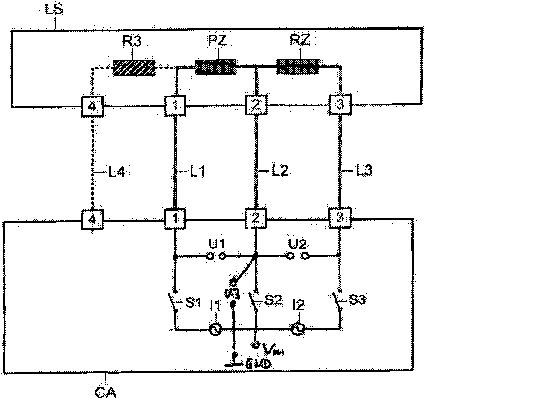
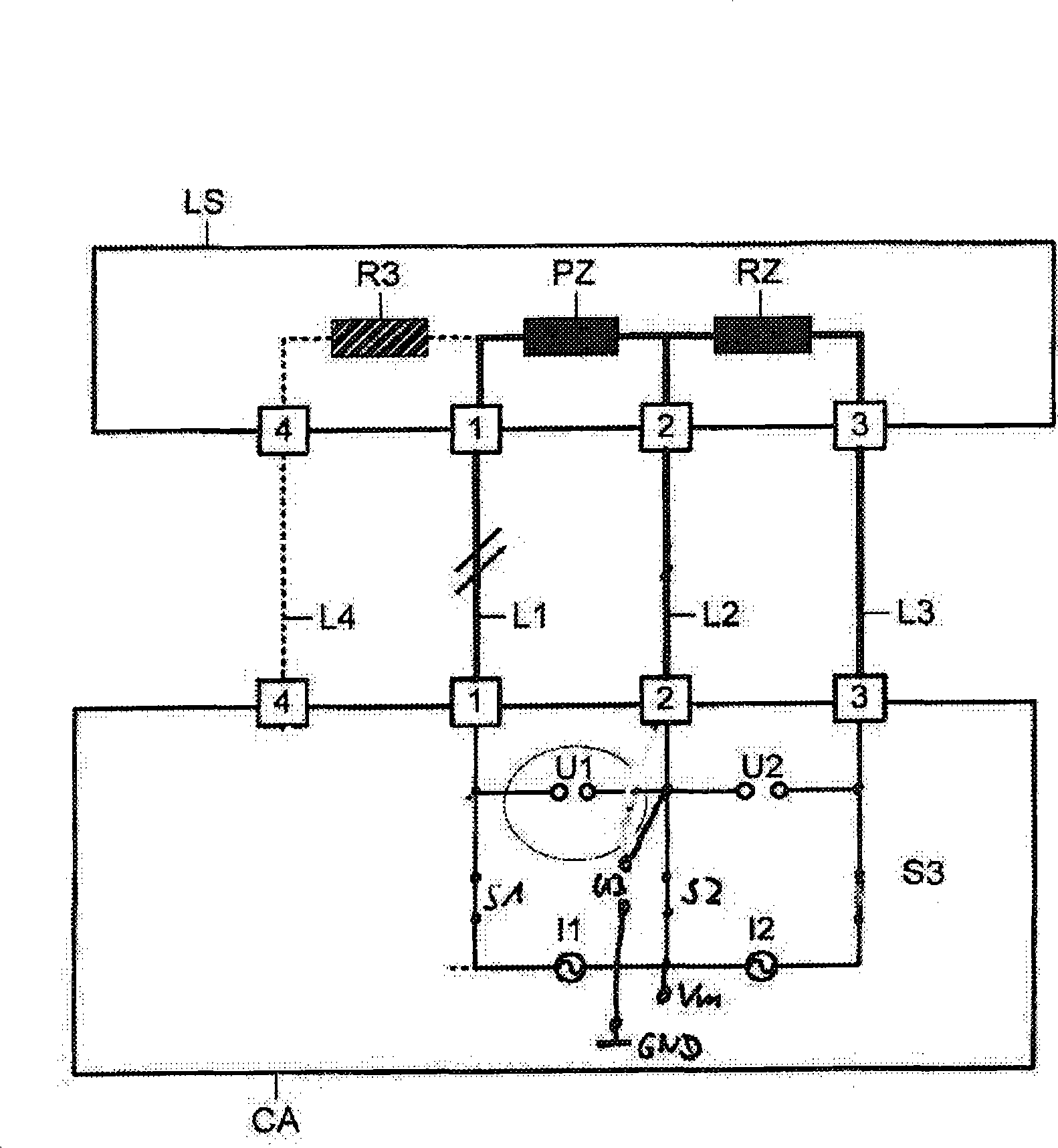
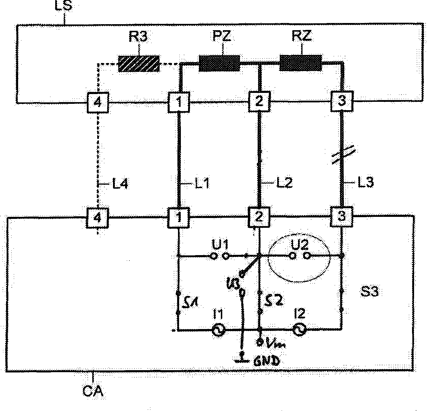
[0018] figure 1 A schematic diagram of a device CA for carrying out the diagnostics according to the invention for the electrical contacting of an exhaust gas sensor LS in the form of a linear exhaust gas probe is shown.

[0019] The exhaust gas sensor LS includes a pump unit PZ as a first unit and a reference unit RZ as a second unit. The pump unit PZ is interconnected between the first terminal 1 and the second terminal 2 of the exhaust gas sensor. A reference unit RZ is interconnected between the second terminal 2 and the third terminal 3 of the exhaust gas sensor LS. These devices are the minimum configuration for an oxygen sensor. exist figure 1 In , an optional balancing resistor R3 is shown in dotted line, which is arranged between the first terminal 1 and the fourth terminal 4 . The balancing resistor R3 is used to compensate for manufacturing tolerances of the probe, ie the resistance value of the pump unit PZ.

[0020] The device CA including all means for diagn...


PUM


Abstract

The invention relates to a method for diagnosing electrical contact connector of an exhaust gas sensor. A method diagnoses electrical contact connection of an exhaust gas sensor, in which two current sources (I1, I2) are used to impress currents into a pump cell (PZ) and a reference cell (RZ) of the exhaust gas sensor. If a line is faulty, the relevant current cannot flow and a voltage on the relevant current source (I1, I2) assumes a high value. If a second line (L2) is faulty, measurement of the voltage on the second terminal (2), which is connected to the connecting point between the two cells (PZ, RZ), provides a low value when the relevant second connection is isolated from the reference-ground potential (Vm) by a second switch (S2), since the cell capacitances have not been able to charge to the reference-ground potential (Vm).

Description

technical field [0001] The invention relates to a method for diagnosing the electrical contact of an exhaust gas sensor having two units, wherein the first of the units is interconnected between a first terminal and a second terminal of the exhaust gas sensor. cells, and interconnecting a second one of the cells between the second terminal and the third terminal. Background technique [0002] Linear oxygen sensors are frequently used as exhaust gas sensors for exhaust gas aftertreatment of internal combustion engines. The first unit is here the so-called pump unit of the oxygen sensor. The second unit is the reference unit for the oxygen sensor. The common terminals of the pump unit and the reference unit are usually connected to a reference potential which has a voltage value of approximately half the supply voltage and which can be interconnected as a virtual reference potential. [0003] Legal regulations require that the exhaust gas sensor be tested with regard to its...

Claims


Application Information

Patent Timeline
IPC IPC(8): F01N11/00G01R31/58
CPCF02D41/1495G01R31/006F02D41/1456F02D41/222Y02T10/40G01N27/4175G01R31/54G01R31/52G01R31/58G01N27/4163G01R31/2832
Inventor J·帕格尔S·施莱格尔
Owner CONTINENTAL AUTOMOTIVE GMBH
Learn More