
Core valve type reactor

A technology of reactors and iron cores, applied in the direction of inductors with magnetic cores, electromagnets with armatures, electromagnets, etc., can solve the problems of large safety hazards, complex structures, high operating costs, etc. The effect of high reliability and low cost

Active Publication Date: 2013-09-04
合肥一通精密机械有限公司
View PDF6 Cites 2 Cited by
  • Summary
  • Abstract
  • Description
  • Claims
  • Application Information

AI Technical Summary

Problems solved by technology

[0007] The purpose of the present invention is to solve the defects of high operating cost, large potential safety hazard and complicated structure in the current limiting device of the reactor, and provide an iron core valve reactor to solve the above problems

Method used


Image

  • Core valve type reactor
  • Core valve type reactor
  • Core valve type reactor

Examples


Embodiment Construction

[0033] In order to have a further understanding and understanding of the structural features of the present invention and the achieved effects, the preferred embodiments and accompanying drawings are used for a detailed description, as follows:

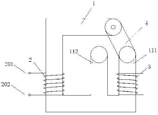
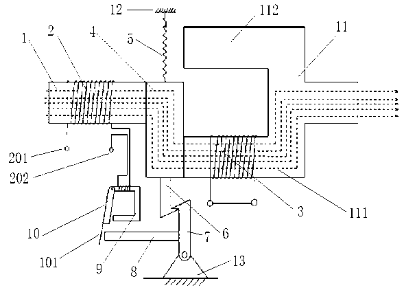
[0034] Such as figure 1 As shown, an iron core valve reactor according to the present invention includes an iron core valve armature arm 4, a main iron core shunt 111, an iron core 1 and a main side reactance winding 2 wound on the iron core 1. The main iron core branch 111 is wound with a short circuit winding group 3, and the main side reactance winding 2 on the iron core 1 is formed by the iron core valve armature arm 4 and the short circuit winding group 3 on the main iron core branch 111. coupling loop. At this time, according to the impedance transformation principle of the ideal transformer 1:1, the impedance of the short-circuit surrounding group 3 on the main iron core shunt 111 is very small and approximately equal to zero...


PUM


Abstract

The invention relates to a core valve type reactor. Compared with the prior art, the reactor solves the problem that a reactor current-limiting device is high in running cost, high in potential risk and complicated in structure. The reactor comprises a core valve armature arm (4), a main circuit shunt (111), a core (1) and a primary reactance winding (2) wound on the core (1), a short circuit ring winding (3) is wound on the main circuit shunt (111), the primary reactance winding (2) on the core (1) and the short circuit ring winding (3) on the main circuit shunt (111) form a coupling loop through the core valve armature arm (4). The core valve type reactor is capable of limiting short-circuit current effectively in depth when short-circuit fault occurs, and has the advantages of low reactive loss in a normal running state, short actuation time during fault and quick response.

Description

[0001] technical field [0002] The invention relates to the technical field of reactors, in particular to an iron core valve reactor. [0003] Background technique [0004] With the rapid increase of power grid capacity and load in the power system, the short-circuit current of the system is also rising, and the short-circuit capacity in many areas has reached and exceeded the breaking capacity of the circuit breaker, which has brought great challenges to the safe and stable operation of the power system. hidden dangers. Short-circuit faults have become one of the most prominent problems that damage power equipment and endanger the safe operation of power systems. In order to solve this problem, the current common method of limiting the short-circuit current of the system is to increase the reactance in the system, that is, to use a high-impedance transformer, to connect reactors in series in the system, to connect the two ends of the current-limiting reactor in parallel ...

Claims


Application Information

Patent Timeline
Patent Type & Authority Applications(China)
IPC IPC(8): H01F17/04H01F27/40H01F7/08H01H71/24
Inventor 高海生
Owner 合肥一通精密机械有限公司
Learn More