
H-1type electrically-controlled magnetic motor

An H-1, magnetic motor technology, applied in the direction of generator/motor, electrical components, etc., can solve the problem of not attracting enough attention, and achieve the effect of simple structure, good speed regulation performance, and low power loss

Active Publication Date: 2013-11-27
赵明珍
View PDF4 Cites 1 Cited by
  • Summary
  • Abstract
  • Description
  • Claims
  • Application Information

AI Technical Summary

Problems solved by technology

Although people have realized that the permanent magnet itself has a strong potential energy and has been well used in the permanent magnet motor, the research, development and utilization of the permanent magnet energy as a new energy source have not attracted enough attention worldwide.

Method used


Image

  • H-1type electrically-controlled magnetic motor
  • H-1type electrically-controlled magnetic motor
  • H-1type electrically-controlled magnetic motor

Examples


Embodiment Construction

[0044] The above and other technical features and advantages of the present invention will be described in more detail below in conjunction with the accompanying drawings.

[0045] H-1 type electronically controlled magnetic motor of the present invention comprises:

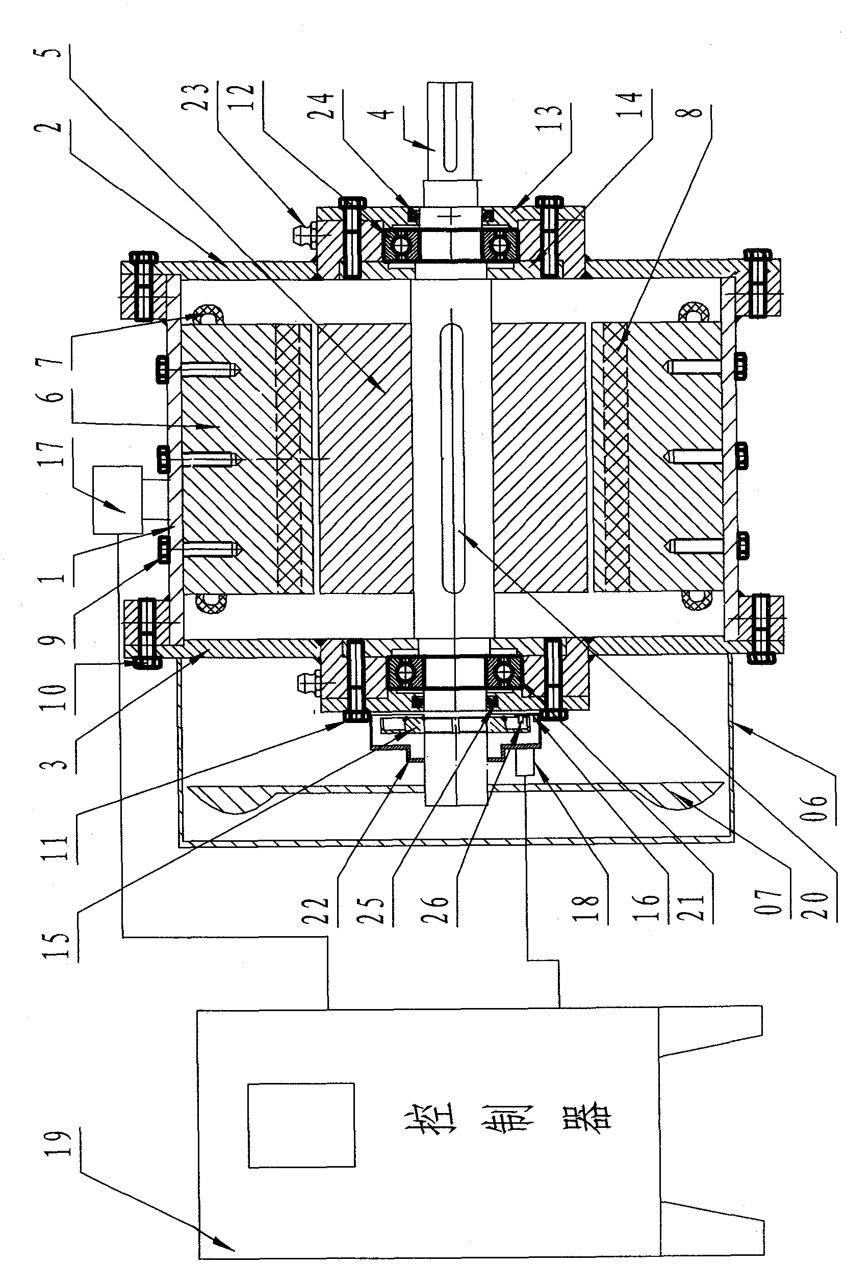
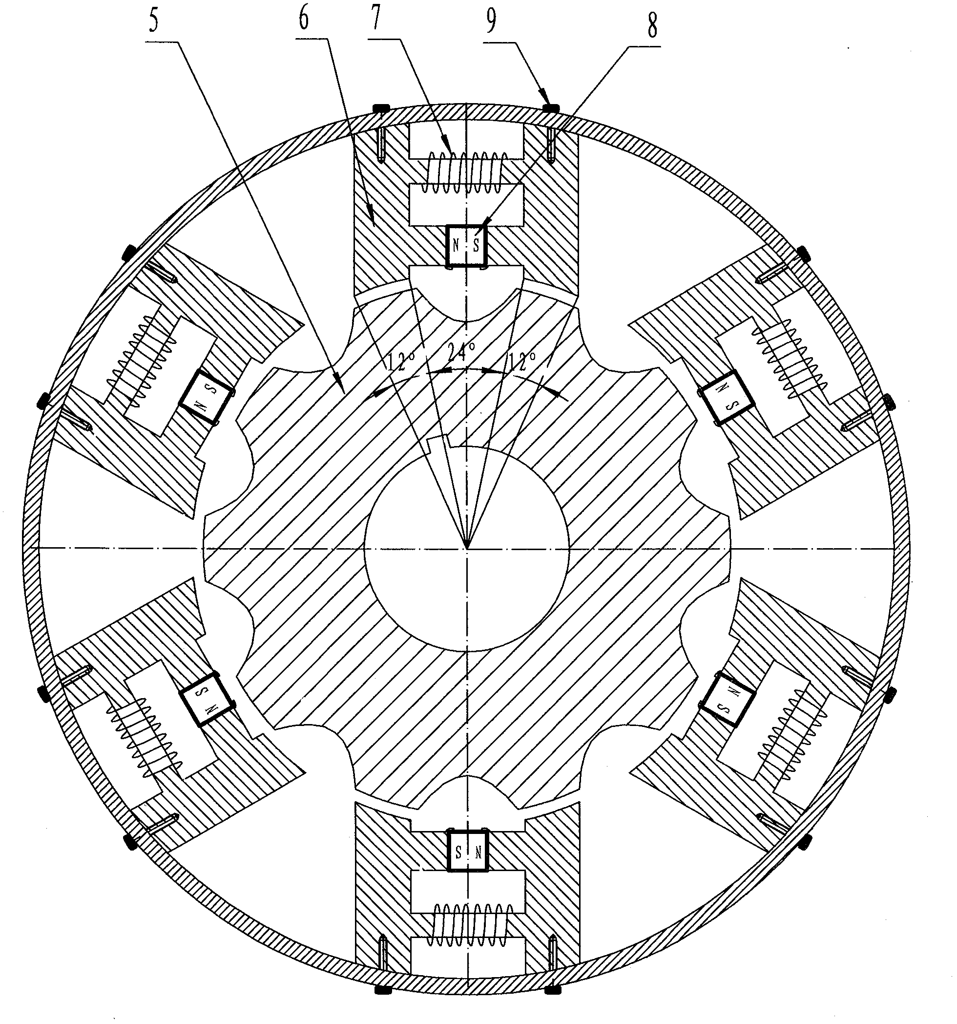
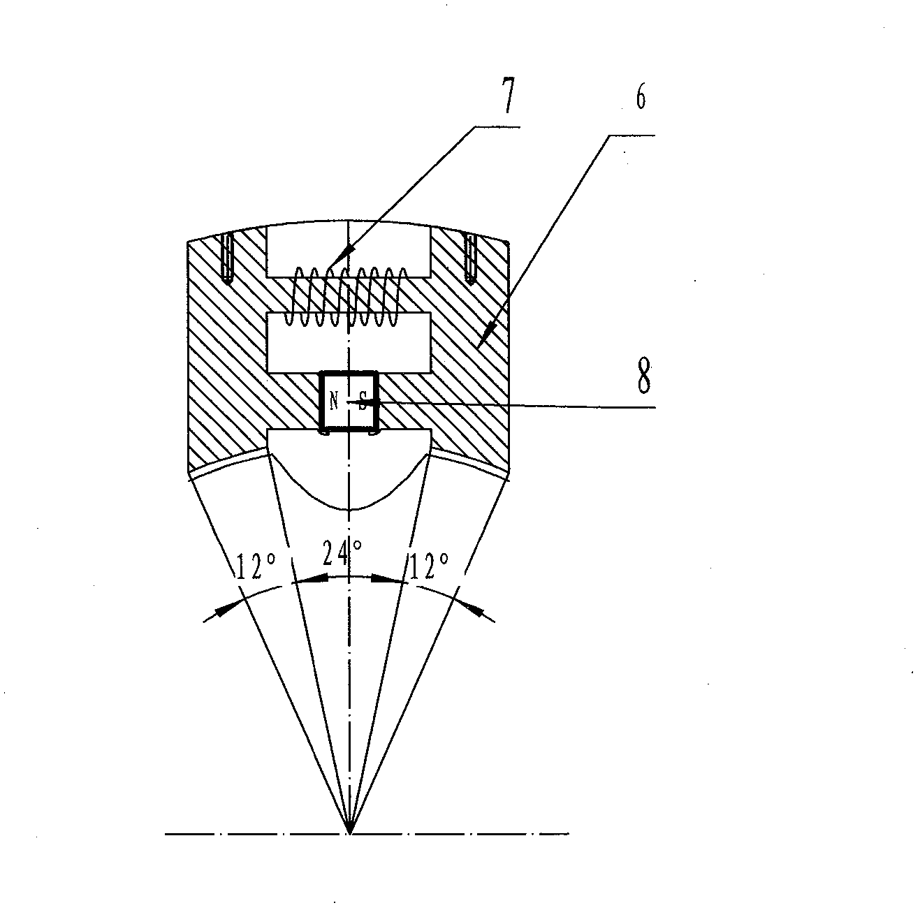
[0046] A magnetic motor mechanical body, and the magnetic motor electric control part; wherein the magnetic motor mechanical body is the entire part of the H-1 type electronically controlled magnetic motor machine, in order to realize the power output of the magnetic motor; the magnetic motor The electromechanical control part is used to realize the power output control of the magnetic motor mechanical body. Such as start, forward rotation, reverse rotation, speed regulation and stop; it also includes monitoring the operation safety of the H-1 type electric control magnetic motor.

[0047] see figure 1 Shown, the sectional structure schematic diagram of the mechanical body of its H-1 type electronically contro...


PUM


Abstract

The invention relates to an H-1type electrically-controlled magnetic motor belonging to the field of permanent magnet energy development. The H-1type electrically-controlled magnetic motor mainly consists of a non-magnetic conductive material case, a front end cover, a rear end cover, a main shaft, a position detection circuit board, a shielding plate, an H-1type stator, a salient pole type rotor, a bearing, an inner bearing pressure cover and an outer bearing pressure cover, wherein the H-1type stator consists of a magnetic conductive material, an electromagnetic coil and a permanent magnet; a stator core and an inner circle wall of the case are connected by bolts; the salient pole type rotor is in key joint with the main shaft; and a trough-type optocoupler of the sensor is mounted on the position detection circuit board on the outer side of the rear end cover of the main shaft. According to the H-1type electrically-controlled magnetic motor, the stator coil is controlled by a three-phase winding through a controller and acts on a magnetic conductive salient pole of the rotor, so as to drive the rotor to rotate, thus the permanent magnet energy can be effectively converted with low power consumption.

Description

technical field [0001] The invention belongs to the field of permanent magnet energy development, and in particular relates to an H-1 type electronically controlled magnetic motor utilizing permanent magnet energy. Background technique [0002] Petroleum, coal and other fossil fuels provide 91% of the world's primary commodity energy. Among them, coal accounts for 28%, and oil accounts for 40%. However, the reserves of fossil fuels on the earth are limited, and due to the unlimited exploitation of human beings, they are rapidly becoming exhausted. According to statistics, human beings burn 4 billion tons of coal and 2.5 billion tons of oil every year; and the annual growth rate is 3%. If things go on like this, scientists estimate that the coal on the earth can last for two to three hundred years, while oil will only be used for five to sixty years. Moreover, excessive development and unlimited consumption of these fossil energy sources will also bring There were extremely...

Claims


Application Information

Patent Timeline
Patent Type & Authority Applications(China)
IPC IPC(8): H02N11/00
Inventor 刘连龙
Owner 赵明珍
Learn More