
Display panel and gate driver thereof

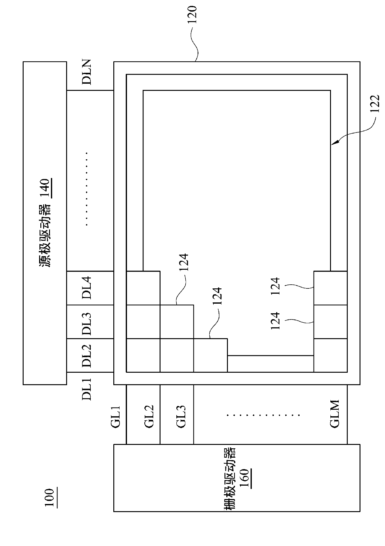
A gate driver and gate driver technology, applied in static indicators, instruments, etc., can solve problems such as difficulty in meeting specifications, limited gate driver area, gate driver circuit architecture, etc., to simplify the circuit structure and reduce the layout area. Effect

Active Publication Date: 2013-09-04
AU OPTRONICS CORP
View PDF3 Cites 14 Cited by
  • Summary
  • Abstract
  • Description
  • Claims
  • Application Information

AI Technical Summary

Problems solved by technology

[0005] However, the above-mentioned technology will be difficult to achieve the required specifications as the current product specifications have higher and higher resolution requirements and narrower frame requirements, so that the area of ​​the final gate driver will still be limited. The size of the circuit structure of the gate driver itself

Method used


Image

  • Display panel and gate driver thereof
  • Display panel and gate driver thereof
  • Display panel and gate driver thereof

Examples


Embodiment Construction

[0036] The following examples are described in detail in conjunction with the accompanying drawings, but the provided examples are not intended to limit the scope of the present invention, and the description of the structure and operation is not intended to limit the order of execution. Any recombination of components Structures, resulting devices with equivalent effects are within the scope of the present invention. In addition, the drawings are for illustration purposes only and are not drawn to original scale. For ease of understanding, the same components will be described with the same symbols in the following description.

[0037] The terms (terms) used throughout the specification and claims, unless otherwise noted, generally have the ordinary meaning of each term used in the field, in the disclosed content and in the special content. Certain terms used to describe the disclosure are discussed below or elsewhere in this specification to provide those skilled in the art ...


PUM


Abstract

The present invention provides a display panel and a gate driver thereof. The gate driver comprises a plurality of cascading driving stages which are used for sequentially outputting a plurality of gate driving signals, and each driving stage includes a mobile deposit unit, a control unit and a buffer unit. The mobile deposit unit is used for generating a shifting signal. The control unit receives a power source signal, used for performing single-pass reversal processing on the shifting signal, and used for outputting the shifting signal after phase reversal at a normal operating state and outputting a high level voltage signal according the power source signal at an off-position state. The buffer unit is used for reception and buffer output of the shifting signal after the phase reversal or the high level voltage signal, so as to serve as one of the gate driving signals.

Description

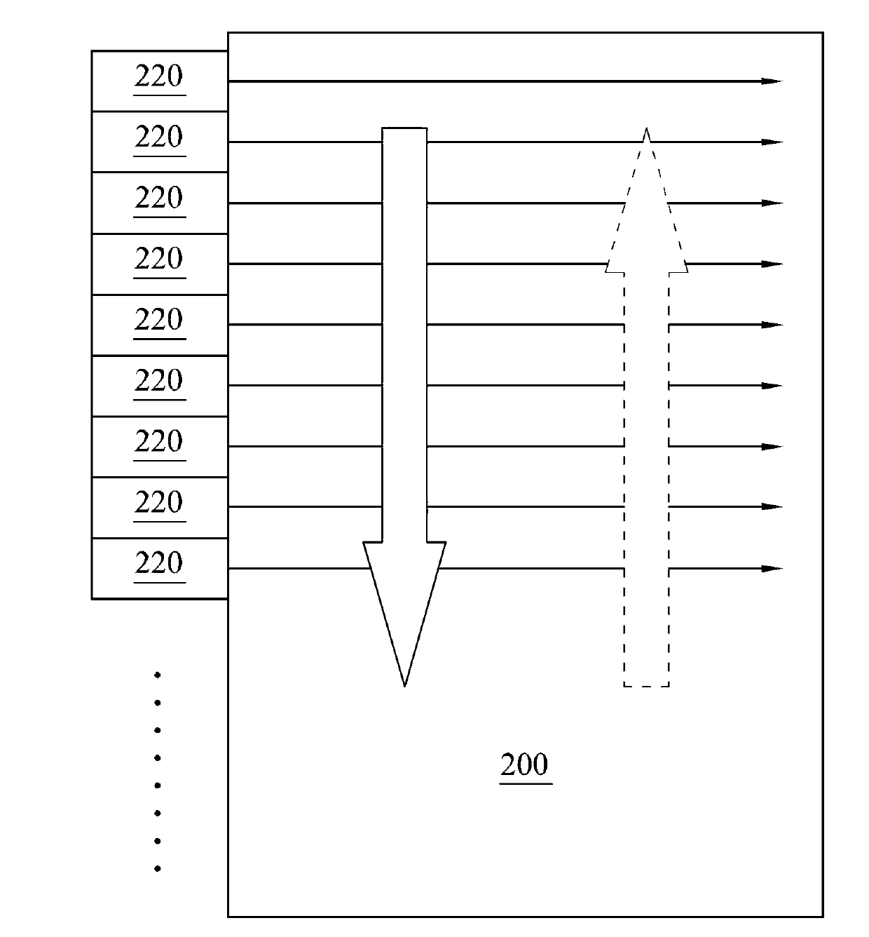
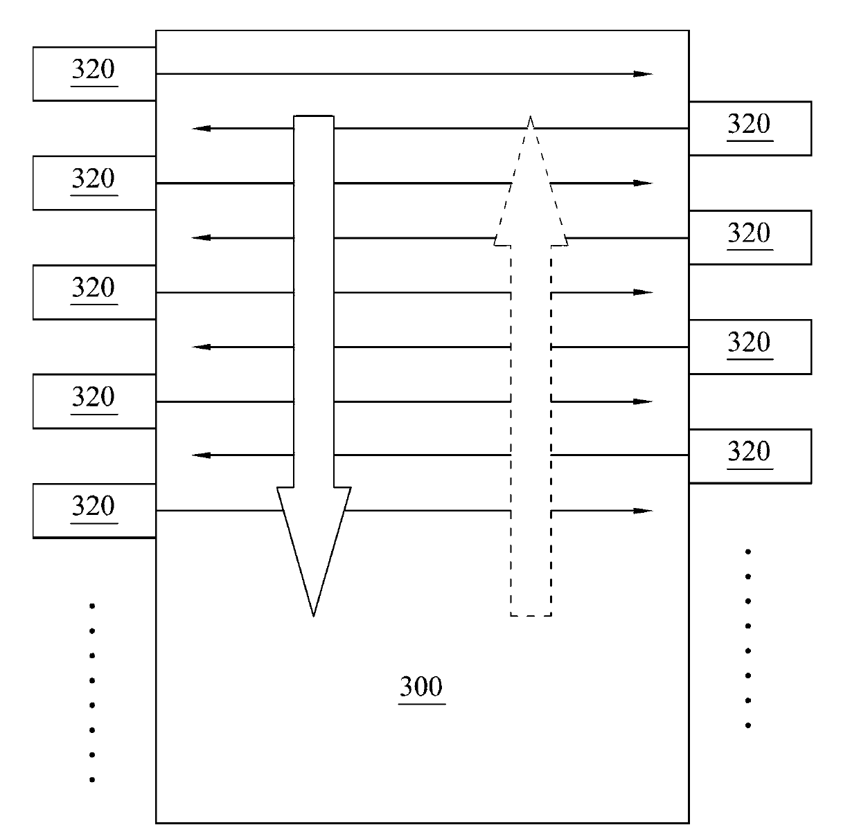
technical field [0001] The present invention relates to a display panel, in particular to a gate driver in the display panel. Background technique [0002] Recently, products of various liquid crystal displays have been considerably popularized. In order to effectively increase the viewing area of ​​the liquid crystal display, display panel technologies suitable for narrow borders have been continuously proposed. For example, taking the gate driver circuit as an example, both the double-sided single-drive shift register circuit architecture and the shared (co-used) shift register architecture can be applied to narrow-frame display panels. [0003] In terms of the double-sided single-drive shift register circuit architecture, the shift register circuits in the gate driver are respectively arranged on both sides outside the pixel area of ​​the display panel, and the shift register circuit on one side is responsible for transmitting odd-numbered levels of gate drive. signal, ...

Claims


Application Information

Patent Timeline
IPC IPC(8): G09G3/36
Inventor 廖伟见李宇轩
Owner AU OPTRONICS CORP
Learn More