
Novel door body structure of vacuum film plating equipment

A technology of coating equipment and door body, applied in vacuum evaporation coating, sputtering coating, ion implantation coating and other directions, can solve the problems of many peripheral components and pipelines, affecting the overall appearance of the equipment, high labor intensity, etc., to achieve universal Good performance, convenient layout and hidden pipelines, neat appearance

Active Publication Date: 2013-09-04
GUANGDONG STRONG METAL TECH
View PDF6 Cites 0 Cited by
  • Summary
  • Abstract
  • Description
  • Claims
  • Application Information

AI Technical Summary

Problems solved by technology

[0003] The technical problem to be solved in the present invention, that is, the purpose of the present invention, one is to overcome the defects of human error, high labor intensity and low efficiency in order to overcome the need for manual observation of the coating process in the existing coating equipment, and the second is to overcome the vacuum chamber of the existing coating equipment There are many peripheral components and pipelines, which affect the overall appearance of the equipment, and provide a door structure for vacuum coating equipment

Method used


Image

  • Novel door body structure of vacuum film plating equipment
  • Novel door body structure of vacuum film plating equipment

Examples


specific Embodiment 1

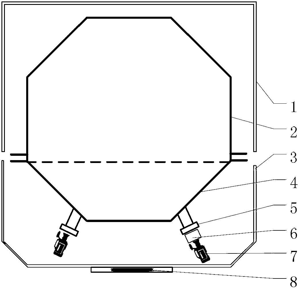
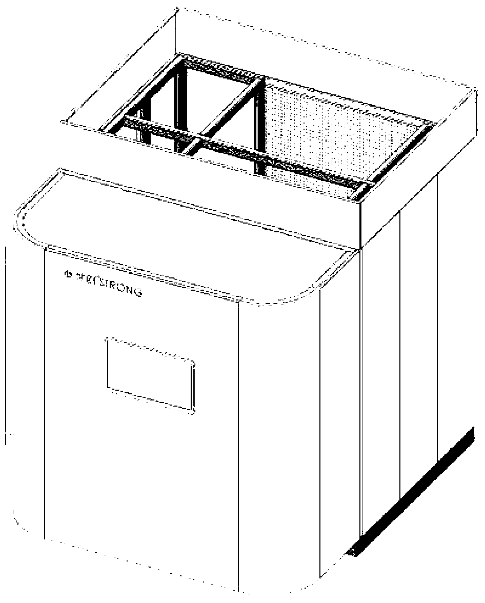
[0016] refer to figure 1 and figure 2 , the door body structure of the coating equipment involved in this embodiment includes a vacuum door body 4 and a vacuum chamber door cover 3, and the vacuum door body 4 is sealed and connected with the vacuum chamber cavity 2 to form a sealed vacuum chamber with a cylindrical structure; A vacuum chamber body cover 1 is provided on the outer surface of the vacuum chamber body 2, and the vacuum chamber is enclosed as a whole by the vacuum chamber door cover 3 and the vacuum chamber body cover 1 to form a vacuum chamber enclosure structure; the vacuum chamber body 4 includes Two or more facades are provided with observation windows 5 on the facades, and camera devices 7 are installed on the observation windows 5; on the front of the vacuum chamber door cover 3, a display screen 8 is installed for video monitoring and process monitoring. .

[0017] In this example:

[0018] An infrared temperature measuring device 6 may be provided on th...


PUM


Abstract

The present invention relates to a novel door body structure of vacuum film plating equipment. The novel door body structure is characterized in that the novel door body structure comprises a vacuum blocking door body and a vacuum chamber door cover, wherein the vacuum blocking door body and a vacuum chamber cavity forms a sealed connection to form a sealed vacuum chamber having a tubular structure, the outer surface of the vacuum chamber cavity is provided with a vacuum chamber cavity cover, the whole vacuum chamber is enclosed through the vacuum chamber door cover and the vacuum chamber cavity cover to form a vacuum chamber enclosing structure, vertical surfaces of the vacuum blocking door body are provided with one or a plurality of observation windows, a camera shooting device is arranged on the observation window, and a vertical surface of the vacuum chamber door cover is provided with a display screen for video monitoring and process monitoring. According to the present invention, the whole outer cover enclosing structure is adopted to form a double-layer door body structure, such that the vertical surfaces of the vacuum chamber cavity and the vacuum chamber door body are conveniently arranged, pipeline hiding is conveniently achieved, and the whole appearance is neat and simple; the infrared temperature measurement device and the camera shooting device can be arranged to real-timely monitor and record working conditions inside the vacuum chamber so as to achieve a purpose of automatic monitoring; and significantly beneficial effects of good versatility, high use rate, convenient use and low cost are provided.

Description

technical field [0001] The invention relates to vacuum coating equipment, in particular to a novel door structure for vacuum coating equipment. It belongs to the technical field of vacuum equipment. technical background [0002] In the prior art, since the workpiece of the vacuum coating equipment is in a closed vacuum environment during the coating process, the working process of the vacuum coating equipment is usually observed on the vacuum chamber, and one or more observation windows are set, and the operator can see through the observation windows, Manually observe and record the temperature in the vacuum chamber and the coating status of the workpiece. This method has defects such as human errors, high labor intensity, low efficiency, and can only be observed but not recorded. In addition, the vacuum chamber of the vacuum coating equipment has many peripheral components and pipelines, which affects the overall appearance of the equipment. Contents of the invention ...

Claims


Application Information

Patent Timeline
Patent Type & Authority Applications(China)
IPC IPC(8): C23C14/00C23C14/52C23C14/54
Inventor 董小虹张中弦梁航黄拿灿
Owner GUANGDONG STRONG METAL TECH
Learn More