
Clamp structure used for eccentricity molding machining of glass mold

A glass mold and eccentric technology, which is applied in the field of fixtures, can solve the problems of glass mold eccentric molding quality, increased difficulty of management, and increased cost of eccentric fixtures, etc., to achieve good clamping adaptability and good generalization , the effect of concise overall structure

Inactive Publication Date: 2013-09-04
ORI MOLD TECH SUZHOU
View PDF14 Cites 1 Cited by
  • Summary
  • Abstract
  • Description
  • Claims
  • Application Information

AI Technical Summary

Problems solved by technology

This kind of fixture structure has the following disadvantages: first, because the corresponding eccentric fixtures need to be made for eccentric molding of glass molds of different specifications, that is, different sizes, the versatility is poor, resulting in an increase in the number of eccentric fixtures and increased difficulty in management and maintenance; , because the blank of the eccentric molding of the glass mold inevitably has deviations in the external dimensions, when it exceeds the limit of the clamping of the eccentric fixture, it cannot be clamped by the eccentric fixture for the eccentric molding of the glass mold; third, Compared with the molding of glass molds of different specifications, the special eccentric clamp has special limitations, thus causing the cost of manufacturing the eccentric clamp to increase and waste resources; The chuck is fixed to the spindle of the lathe, so the concentricity clamping requirements with the spindle of the lathe are extremely strict. If there is a slight eccentricity, the quality of the eccentric molding of the processed glass mold will be affected, or even scrapped.

Method used


Image

  • Clamp structure used for eccentricity molding machining of glass mold
  • Clamp structure used for eccentricity molding machining of glass mold
  • Clamp structure used for eccentricity molding machining of glass mold

Examples


Embodiment

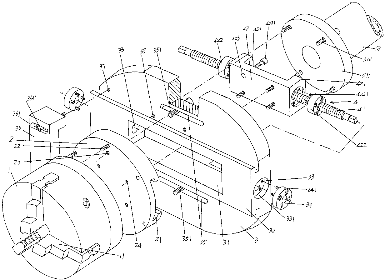
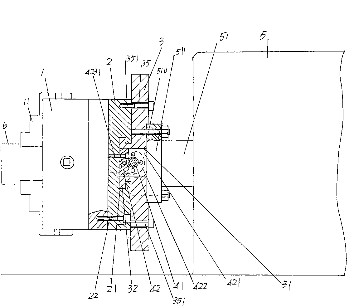
[0021] See figure 1 and figure 2 , for the convenience of the public's understanding, the applicant shows the lathe spindle 51 of the headstock 5 of the CNC lathe in the figure, and a spindle disk 511 is formed on the end face of the lathe spindle 51, on the spindle disk 511 and around the spindle disk A group of spindle disc connecting screws 5111 are arranged at intervals in the circumferential direction of the spindle disc 511 .

[0022] The following description is aimed at the parts that constitute the clamp structure system for the eccentric molding of the glass mold of the present invention. A jaw plate 1 is provided, and the side facing outwards in the use state of the jaw plate 1 is the back One set of jaws 11 is provided on one side of the connection plate 2, and the number of the set of jaws 11 is three. Since the structure and function of the jaw plate 1 belong to the known technology, the applicant will not repeat them here.

[0023] Provide a connection plate ...


PUM


Abstract

The invention provides a clamp structure used for eccentricity molding machining of a glass mold, and belongs to the technical field of tool clamps used for glass mold machining. The clamp structure comprises a clamping jaw plate, a connection plate and a guide rail plate, wherein the side, opposite to the connection plate, of the clamping jaw plate is provided with a set of clamping jaws, the connection plate is fixed to the side, opposite to the claming jaws of the clamping jaw plate, a guide rail sliding groove is formed in one side, facing the guide rail plate, of the connection plate, the guide rail plate is connected with the connection plate, an adjustment base sliding cavity is arranged in the guide rail plate, a guide rail is arranged on one side, facing the connection plate, of the guide rail plate, the guide rail is matched with the guide rail sliding groove, and a center adjustment mechanism is arranged in the adjustment base sliding cavity to be connected with the connection plate. The clamp structure has the advantages that the universal degree is high, the number of clamps is reduced, resources are saved, good clamping adaptability is achieved for eccentricity molding outer circle differences of the glass mold, the overall structure is concise, operation is convenient, the concentricity of a lathe main shaft and the clamp structure can be guaranteed, and clamping efficiency is improved.

Description

technical field [0001] The invention belongs to the technical field of tooling fixtures for glass mold processing, and in particular relates to a fixture structure for eccentric molding of glass molds. Background technique [0002] As known in the industry, the mold is the primary part of a complete set of glass molds, and it is used as a mold for stamping the inner cavity of the initial shape (also called the prototype) of the bottle and can. The function of molding is: firstly, to ensure the overall molding of the glass container, and secondly, to completely stamp the molten glass material into the inner cavity and valve head of the mold by stamping, so as to ensure that the subsequent prototype, that is, the blank of the initial mold, is formed into a glass container such as a bottle by the forming mold. . [0003] A representative example of the aforementioned eccentric molding of the glass mold is a mold used to form a glass cup with a handle. For the sake of saving gl...

Claims


Application Information

Patent Timeline
IPC IPC(8): B23Q3/12
Inventor 戈剑鸣
Owner ORI MOLD TECH SUZHOU
Learn More