
A flexible multiferroic device

A multiferroic and flexible technology, applied in the direction of electric solid devices, devices using electro-magnetic effects, electrical components, etc., can solve the problem of weakening of the pinning and binding effect of the magnetoelectric coupling effect of flexible multiferroic devices, and achieve good Industrial practical application prospects, large magnetoelectric coupling effect, and strong scalability

Active Publication Date: 2015-09-30
NINGBO INST OF MATERIALS TECH & ENG CHINESE ACADEMY OF SCI
View PDF6 Cites 0 Cited by
  • Summary
  • Abstract
  • Description
  • Claims
  • Application Information

AI Technical Summary

Problems solved by technology

[0005] However, flexible materials are often amorphous. When using flexible multiferroic devices made of flexible multiferroic materials, it is generally necessary to place the flexible multiferroic material on a rigid support, or to limit the flexible multiferroic material to a rigid support. Therefore, in actual use, the magnetoelectric coupling effect of the flexible multiferroic device is often weakened due to the pinning effect of the rigid support or the package.

Method used


Image

  • A flexible multiferroic device
  • A flexible multiferroic device
  • A flexible multiferroic device

Examples


Embodiment 1

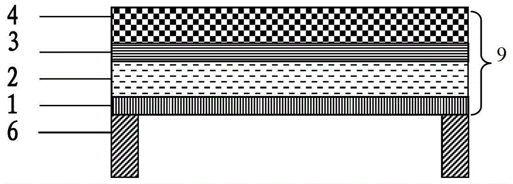
[0035] In this example, if figure 1 As shown, the flexible multiferroic device mainly includes a flexible multiferroic material 9 , and a support body 6 connected to the bottom of the flexible multiferroic material 9 for supporting the flexible multiferroic material 9 .

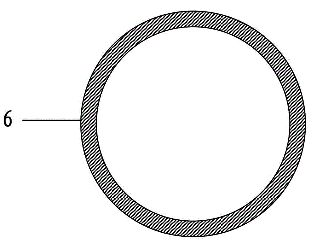
[0036] The support body 6 is a hollow cylindrical structure, and its cross section is as follows: figure 2 Shown as a circular ring, the support body 6 is distributed on the bottom edge of the flexible multiferroic material 9, and the contact surface with the flexible multiferroic material 9 is circular. Supported by the contact surface, the flexible multiferroic material 9 is suspended.

[0037] like figure 1 As shown, the flexible multiferroic material 9 includes bottom electrode 1 , flexible ferroelectric substrate 2 , top electrode 3 , and top ferromagnetic material layer 4 from bottom to top. Among them, the flexible ferroelectric substrate 2 is made of PVDF; the top ferromagnetic material layer 4 is...

Embodiment 2

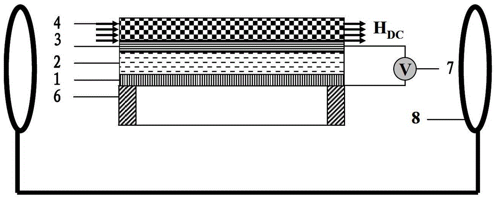
[0047] In this example, if Figure 6 As shown, the flexible multiferroic device mainly includes a flexible multiferroic material 9 , and a support body 6 connected to the bottom of the flexible multiferroic material 9 for supporting the flexible multiferroic material 9 .

[0048] The support body 6 is composed of two identical columnar bodies. Its cross-section is as Figure 7 Shown as a rectangle, the support body 6 is distributed on both ends of the bottom edge of the flexible multiferroic material 9, and the contact surface with the flexible multiferroic material 9 is composed of two independent, non-overlapping, rectangular sub-contact surfaces . Supported by the contact surface, the flexible multiferroic material 9 is suspended.

[0049] like Figure 6 As shown, the flexible multiferroic material 9 is as follows from bottom to top: bottom ferromagnetic material layer 5 , bottom electrode 1 , flexible ferroelectric substrate 2 , top electrode 3 , and top ferromagnetic ...


PUM


Abstract

The invention provides a flexible multiferroic device of a novel structure. The flexible multiferroic device comprises a flexible multiferroic material and a supporting body, wherein a contact surface between the supporting body and the flexible multiferroic material is arranged on the bottom edge of the flexible multiferroic material, and the flexible multiferroic material is of a suspended shape with the contact surface as a support. Experiments prove that on one hand, the structure ensures 'self-supporting performance' of the flexible multiferroic device, and therefore the situation that the magnetoelectric coupling effect is weakened greatly due to the fact that the flexible multiferroic material is under the pinning constraint action because the bottom face of the flexible multiferroic material is directly placed on surfaces of other rigid supporting bodies can be avoided; on the other hand, the 'flexibility' of the flexible multiferroic device is ensured. Due to the fact that most of the flexible multiferroic material is of the suspended shape, vibration generated in a magnetoelectric coupling process is magnified as far as possible, and a strong magnetoelectric coupling effect can be achieved. Therefore, the flexible multiferroic device has a wide application prospect in the magnetic sensor field, the energy collection field and other fields.

Description

technical field [0001] The invention relates to the technical field of multiferroic materials, the field of magnetic sensors and energy collection, and in particular to a flexible multiferroic device that can be applied to magnetic sensing and energy collection equipment. Background technique [0002] Multiferroic materials are new multifunctional materials that combine ferroelectricity, ferromagnetism and ferroelasticity. Due to the coupling interaction between various "ferroic properties", multiferroic materials have some unique physical effects. For example, through the coupling effect between ferroelectricity and ferromagnetism, ferroelectricity can be controlled by magnetic field, or ferroelectricity can be controlled The use of electric fields to control magnetism, including magnetic moment orientation, etc. [0003] Multiferroic materials have important application prospects in the field of weak magnetic field detection. Studies have shown that the expected sensitivi...

Claims


Application Information

Patent Timeline
Patent Type & Authority Patents(China)
IPC IPC(8): H01L43/00H01L43/02H01L43/12H10N50/01H10N50/80
Inventor 谢亚丽刘宜伟李润伟詹清峰
Owner NINGBO INST OF MATERIALS TECH & ENG CHINESE ACADEMY OF SCI
Learn More