Eureka AIR delivers breakthrough ideas for toughest innovation challenges, trusted by R&D personnel around the world.

Method for measuring atmospheric optical turbulent current profile based on imaging laser radar of laser light beam

A technology of laser radar and beam of light, applied in the field of atmospheric optics, can solve the problem of low temporal and spatial resolution, achieve high temporal resolution, easy implementation, and high spatial resolution

Active Publication Date: 2013-08-28
ANHUI INST OF OPTICS & FINE MECHANICS - CHINESE ACAD OF SCI
View PDF2 Cites 15 Cited by
  • Summary
  • Abstract
  • Description
  • Claims
  • Application Information

AI Technical Summary

Problems solved by technology

The current relatively mature laser active technology for measuring turbulence intensity profiles is mainly based on the DIM Lidar method, but this method has a low temporal and spatial resolution for measuring a set of turbulence profiles

Method used


Image

  • Method for measuring atmospheric optical turbulent current profile based on imaging laser radar of laser light beam
  • Method for measuring atmospheric optical turbulent current profile based on imaging laser radar of laser light beam
  • Method for measuring atmospheric optical turbulent current profile based on imaging laser radar of laser light beam

Examples


Embodiment Construction

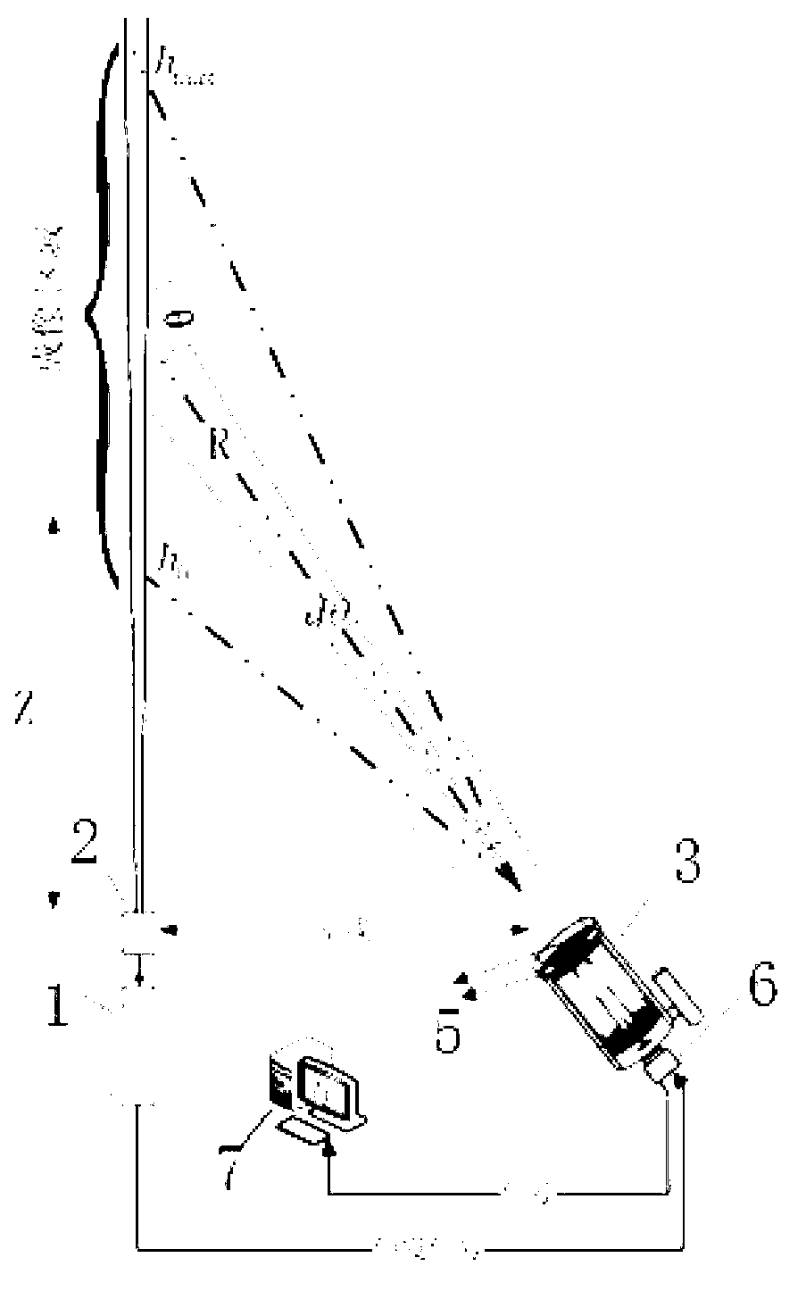
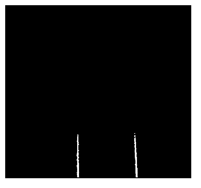
[0020] See attached figure 1 , 3 . The method of measuring the atmospheric optical turbulence profile based on the imaging lidar of the laser beam, first forms a double image of the laser beam, then counts the fluctuation characteristics of the angle of arrival of the double image, and finally performs the measurement and calculation of the turbulence profile; specifically includes the following steps:

[0021] (1) Laser emitting unit: The laser emitting unit includes a laser 1 and a beam expander 2. The laser 1 emits vertically upward along the zenith direction, and the beam expander 2 expands the beam emitted by the laser 1 to suppress the divergence angle of the beam to form a beam. Beam beam;

[0022] (2) Optical receiving unit: The optical receiving unit includes a telescope 3, a pupil plate 4, a wedge mirror 5 and a CCD 6, and a two-hole Hartmann pupil plate 4 is placed in front of the main mirror of the telescope 3, and the pupil plate 4 is installed The optical wedg...


PUM


Abstract

The invention discloses a method for measuring an atmospheric optical turbulent current profile based on an imaging laser radar of a laser light beam. Laser light is emitted vertically upward by a laser emission unit, beam expanding is carried out on the laser light through a beam expanding mirror to reduce a divergence angle of the laser light, and the light beam is formed; a pupil plate is installed at the front end of a telescope objective lens of an optical receiving unit, an optical wedge mirror is installed on the pupil plate, a CCD is installed at the rear end of a telescope, and when the telescopic mirror is aligned to the laser light beam to image the light beam, due to beam split action of a light wedge, two light beam images in the vertical direction occur on a CCD target face; light beam images formed by various image elements of the CCD correspond to light beams on different heights, the jitter amount of the CCD images in the horizontal direction on the different heights are counted through the adoption of a differential image moving method, turbulent current information in the route of an imaging receiving face of the laser light beam can be obtained, then turbulent current information on different integral paths is analyzed, and a turbulent current strength profile is obtained. The method has high time resolution and space resolution, and is easy to implement and complete in theory.

Description

technical field [0001] The technical invention relates to the field of atmospheric optics, in particular to a method for measuring atmospheric optical turbulence profiles by imaging lidar based on laser beams. Background technique [0002] When the laser is transmitted in the turbulent atmosphere, the fluctuation of the refractive index caused by the atmospheric turbulence leads to the distortion of the laser wavefront, which destroys the coherence of the laser and directly affects the transmission effect. For high-resolution photoelectric imaging telescopes to perform optical observations on the ground, atmospheric turbulence reduces the target imaging resolution, affecting tracking, positioning accuracy and correction efficiency of adaptive optics. The turbulence intensity profile is a quantitative description of the optical turbulence intensity and is one of the most important parameters reflecting the optical characteristics of atmospheric turbulence. Therefore, real-ti...

Claims


Application Information

Patent Timeline
Patent Type & Authority Applications(China)
IPC IPC(8): G01S17/89
Inventor 黄宏华崔朝龙朱文越侯再红黄印博吴毅饶瑞中
Owner ANHUI INST OF OPTICS & FINE MECHANICS - CHINESE ACAD OF SCI
Why Eureka
Eureka Blog
Learn More