
Rotation torque sensor supplying power by adoption of dynamic transformer in coupling mode

A torque sensor and transformer coupling technology, applied in torque measurement, instrumentation, power measurement, etc., can solve problems such as unreliable work, circuit failure, large friction loss between brushes and slip rings, etc., to expand the application range and reduce temperature drift The coefficient is small, the effect of solving the problem of anti-interference

Inactive Publication Date: 2013-08-28
BENGBU COLLEGE
View PDF5 Cites 9 Cited by
  • Summary
  • Abstract
  • Description
  • Claims
  • Application Information

AI Technical Summary

Problems solved by technology

[0003] At present, the torque measurement of rotating equipment mainly adopts three methods: pure magnetoelectric, photoelectric and metal slip ring. Among them, the metal slip ring rotary torque sensor belongs to contact measurement. For high-speed rotating equipment, the brush and The friction loss between the slip rings is large, which is not conducive to long-term use; the pure magnetoelectric torque measurement device uses magnetic coupling to transmit the signal to the torque strain gauge, and its modulation and demodulation circuits are relatively complicated, and are easily affected by rotating equipment, especially It is the magnetic field interference of large-scale rotating equipment, which causes large measurement errors and unreliable work; the pure photoelectric encoder supplies power to the rotating strain gauge, and uses monocrystalline silicon or polycrystalline silicon photovoltaic cells with low conversion efficiency for power supply, and the small environment has a large temperature rise, resulting in photoelectric The transmitting and receiving characteristics of the transmitting and receiving devices change, resulting in circuit failure. On the other hand, due to the large temperature rise of the small environment, the output temperature drift of the rotary torque sensor is large.

Method used


Image

  • Rotation torque sensor supplying power by adoption of dynamic transformer in coupling mode
  • Rotation torque sensor supplying power by adoption of dynamic transformer in coupling mode
  • Rotation torque sensor supplying power by adoption of dynamic transformer in coupling mode

Examples


Embodiment Construction

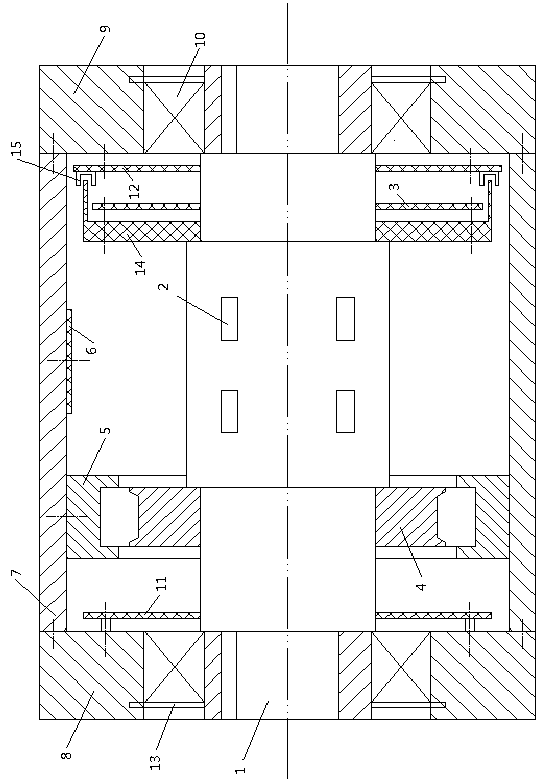
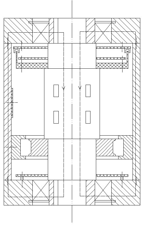
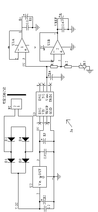
[0018] A rotary torque sensor that adopts a dynamic transformer coupling power supply, including an elastic rotary shaft 1, a strain gauge 2 is pasted on the shaft, a support plate 14 for installing a signal conditioning and infrared photoelectric emission circuit board 3, and a secondary coil 4 of a dynamic transformer are all fixed on the shaft body of the elastic rotating shaft 1, the F / V and V / I conversion circuit board 6, and the primary coil 5 of the dynamic transformer are all fixed on the shell of the shell 7, the primary coil 5 of the dynamic transformer and the dynamic The secondary coil 4 of the transformer is coupled, the two ends of the casing 7 are respectively fixed with end caps, the elastic rotating shaft 1 is installed on the end caps through the bearing 10, the primary oscillation driving circuit board 11 of the dynamic transformer, the infrared receiving and pulse shaping circuit board 12 are all Fixed on the end cover, a plurality of teeth are evenly spaced...


PUM


Abstract

The invention relates to a rotation torque sensor supplying power by the adoption of a dynamic transformer in a coupling mode. The rotation torque sensor supplying the power by the adoption of the dynamic transformer in the coupling mode comprises an elastic rotating shaft. A strain gage is adhered to the shaft body of the elastic rotating shaft; both a signal conditioning and infrared photoelectric emission circuit board and a secondary coil of the dynamic transformer are fixedly arranged on the shaft body of the elastic rotating shaft; both an F / V and V / I conversion circuit board and a primary coil of the dynamic transformer are fixedly arranged on the shell body of a shell; the primary coil of the dynamic transformer is coupled to the secondary coil of the dynamic transformer; two ends of the shell are respectively and fixedly provided with an end cover; the elastic rotating shaft is installed on end covers through bearings; both a primary oscillation drive circuit board of the dynamic transformer and an infrared receiving and pulse shaping circuit board are fixedly arranged on the end covers. The rotation torque sensor supplying the power by the adoption of the dynamic transformer in the coupling mode effectively solves the problems that a purely-photoelectric-type rotation torque sensor supplies power through photocells so as to cause large temperature rise, and meanwhile effectively solves the anti-interference problem of a purely-magneto-electricity-type rotation torque sensor, can output a plurality of types of signals such as frequency signals, current signals and voltage signals, and enlarges application ranges.

Description

technical field [0001] The invention relates to the field of rotary torque sensors, in particular to a rotary torque sensor that adopts dynamic transformer coupling for power supply. Background technique [0002] Different from the general torque sensor, the most important part of the rotary torque sensor is to realize the non-contact measurement of the dynamic load of the rotating equipment, which needs to solve the problem of dynamic power supply and non-contact transmission signal in the process of rotating torque measurement. series of questions. [0003] At present, the torque measurement of rotating equipment mainly adopts three methods: pure magnetoelectric, photoelectric and metal slip ring. Among them, the metal slip ring rotary torque sensor belongs to contact measurement. For high-speed rotating equipment, the brush and The friction loss between the slip rings is large, which is not conducive to long-term use; the pure magnetoelectric torque measurement device us...

Claims


Application Information

Patent Timeline
Patent Type & Authority Applications(China)
IPC IPC(8): G01L3/12
Inventor 乔爱民张炜罗少轩何建新张新庭
Owner BENGBU COLLEGE
Learn More