
Resistance heating furnace

A resistance heating and resistance technology, applied in electric furnace heating, furnace heating elements, furnaces, etc., can solve the problems of many heating elements, large maintenance costs, large heating elements, etc., to achieve simple maintenance process, improve economic benefits, and large heating power. Effect

Inactive Publication Date: 2013-08-28
王子金
View PDF8 Cites 2 Cited by
  • Summary
  • Abstract
  • Description
  • Claims
  • Application Information

AI Technical Summary

Problems solved by technology

[0002] Electric heating furnaces are commonly used heating equipment in chemical production processes such as acid production and chemical fertilizers. There are two commonly used electric heating furnaces, one is electric heating tube type electric furnace, the other is resistance wire type electric furnace, and electric heating tube type electric furnace is not resistant to High temperature, easy damage, many heating elements, inconvenient wiring, and high maintenance costs in the later period; and resistance wire electric furnaces, there are problems such as large single set of heating elements, large hoisting flange, and heavy weight, such as the applicant's patent No. It is the electric heating furnace involved in the invention patent of 200710304349.4. This kind of electric resistance wire electric furnace needs to be hoisted by large hoisting equipment when it is maintained.

Method used


Image

  • Resistance heating furnace
  • Resistance heating furnace
  • Resistance heating furnace

Examples


Embodiment Construction

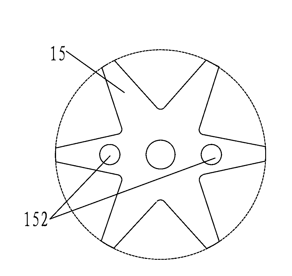
[0012] Such as figure 1 , 2 As shown, the resistance heating furnace of the present invention includes a furnace body 02 and a plurality of resistance heating elements 01, the furnace body 02 is provided with an insulating layer 22, the resistance heating element 01 includes a terminal post 11, and the terminal post 11 is covered with a rainproof cap 14, The protective casing 12, the resistance heating element 01 also includes a hoisting upper flange 13, a hoisting hanging wire insulating frame 15, a resistance wire 17, a hoisting rod 19, the hoisting upper flange 13 is welded to the lower end of the protective sleeve 12, and the hoisting hanging wire insulating frame 15 is columnar, such as image 3 As shown, two lifting rod holes 152 extending axially are arranged in it, and the two lifting rod holes 152 are symmetrical to each other along the axis of the lifting hanging wire insulation framework 15, and the two lifting rods 19 are respectively located in the two lifting ro...


PUM


Abstract

The invention relates to a resistance heating furnace which comprises a furnace body and at least one resistance heating element, wherein the resistance heating element comprises a binding post. A protective sleeve is sleeved outside the binding post, and the resistance heating element further comprises an upper lifting flange, a lifting wire hanging insulation framework, a resistance wire and lifting rods, wherein the upper lifting flange is fixed at the lower end of the protective sleeve, two lifting rod holes are formed in the columnar lifting wire hanging insulation framework, the two lifting rods are located in the two lifting rod holes respectively, the resistance wire is wound on the outer wall of the lifting wire hanging insulation framework, the lifting wire hanging insulation framework and the upper ends of the lifting rods are all fixed on the lower surface of the upper lifting flange, one end of the resistance wire is communicated with the binding post, the other end of the resistance wire is communicated with the furnace body through the lifting rods, at least one lower lifting flange is arranged on the outer wall of the furnace body, and the upper lifting flange of each resistance heating element is fixed with one lower lifting flange. According to the resistance heating furnace, each heating element is small in size and light in weight, each heating element is independently installed, maintenance is simple, large-scale lifting devices are not required, and maintenance cost is low.

Description

technical field [0001] The invention relates to an electric heating device, in particular to an electric heating device with an electrical connector specially suitable for high temperature. Background technique [0002] Electric heating furnaces are commonly used heating equipment in chemical production processes such as acid production and chemical fertilizers. There are two commonly used electric heating furnaces, one is electric heating tube type electric furnace, the other is resistance wire type electric furnace, and electric heating tube type electric furnace is not resistant to High temperature, easy damage, many heating elements, inconvenient wiring, and high maintenance costs in the later period; and resistance wire electric furnaces, there are problems such as large single set of heating elements, large hoisting flange, and heavy weight, such as the applicant's patent No. It is the electric heating furnace involved in the invention patent of 200710304349.4. This ki...

Claims


Application Information

Patent Timeline
Patent Type & Authority Applications(China)
IPC IPC(8): F27D11/02H05B3/62
Inventor 王子金
Owner 王子金
Learn More