
Cooling device of large-scale motor

A technology for cooling devices and large motors, which is applied in the direction of electromechanical devices, cooling/ventilation devices, electrical components, etc., and can solve problems such as difficult to equip air temperature adjustment devices, temperature rise of motor windings, and increased heat generation of motors, so as to save occupied space , obvious cooling effect and long service life

Inactive Publication Date: 2013-08-28
BAOSTEEL DEV CO LTD
View PDF0 Cites 7 Cited by
  • Summary
  • Abstract
  • Description
  • Claims
  • Application Information

AI Technical Summary

Problems solved by technology

This type of motor mostly adopts its own fan, which cools the motor with the operation of the motor, and is installed in different locations according to different uses. In large-scale metallurgical industries, this type of motor is mostly installed in basements or places where the temperature is harsh. , these areas are difficult to be equipped with air conditioning devices, and there are a lot of heating equipment, but with the acceleration of production rhythm and the increase of service life, the performance index of the motor is declining year by year, which is manifested in the temperature rise of the motor winding due to aging, resulting in motor failure The heat generation is greatly increased, and such large motors are often installed in a small space, which is difficult to solve directly through ventilation. In order to ensure the safe production of the motor, a simple and practical, high control performance, reliable operation, and low failure rate are sought for large-scale motor cooling. Devices are the goal pursued by maintainers in this field

Method used


Image

  • Cooling device of large-scale motor
  • Cooling device of large-scale motor

Examples


Embodiment Construction

[0017] The technical solutions of the present invention will be further described below in conjunction with the accompanying drawings and embodiments.

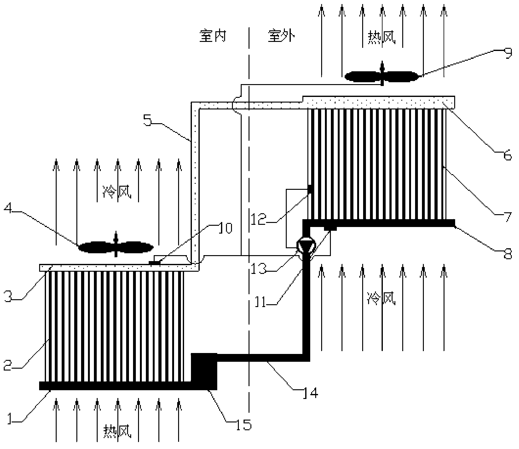
[0018] see figure 1 , figure 2 The cooling device for a large motor shown includes an evaporation mechanism, a condensation mechanism and a temperature sensor;

[0019] The evaporation mechanism is set at the fan inlet of the large indoor motor 4. The evaporation mechanism includes the evaporator heat pipe group 2. The upper end of the evaporator heat pipe group 2 is connected with the evaporator gas collection pipe 3, and the lower end of the evaporator heat pipe group 2 is separated from the evaporator. Tube 1 is connected;

[0020] The condensing mechanism is located outdoors, and the condensing mechanism includes a condenser heat pipe group 7, the upper end of the condenser heat pipe group 7 communicates with the condenser gas distribution pipe 6, the lower end of the condenser heat pipe group 7 communicates with the co...


PUM


Abstract

The invention discloses a cooling device of a large-scale motor. The cooling device comprises an evaporator heat pipe set, a condenser heat pipe set and temperature sensors, wherein the upper end of the evaporator heat pipe set is communicated with an evaporator air collecting pipe, the lower end of the evaporator heat pipe set is communicated with an evaporator liquid separating pipe, the upper end of the condenser heat pipe set is communicated with a condenser air separating pipe, the lower end of the condenser heat pipe set is communicated with a condenser liquid collecting pipe, a condenser fan is arranged at the back side of the condenser liquid collecting pipe, the evaporator air collecting pipe is communicated with the condenser air separating pipe through an air pipe connecting pipe, the evaporator liquid separating pipe is communicated with the condenser liquid collecting pipe through a liquid pipe connecting pipe, the temperature sensors are installed on the evaporator air collecting pipe and the condenser liquid collecting pipe respectively, and the temperature sensors and the condenser fan are respectively connected with a controller. The cooling device can lower the temperature of circulating air entering the motor, can improve efficiency of heat exchange between the air and a motor winding, and obviously cools the motor.

Description

technical field [0001] The invention relates to motor equipment maintenance technology, and more specifically relates to a large-scale motor cooling device. Background technique [0002] In modern industrial production, especially in metallurgical enterprises, large motors are an indispensable equipment, which plays a very important role in the production of strip steel products, fluid transportation, and in ensuring product quality and safe production. This type of motor mostly adopts its own fan, which cools the motor with the operation of the motor, and is installed in different locations according to different uses. In large-scale metallurgical industries, this type of motor is mostly installed in basements or places where the temperature is harsh. , these areas are difficult to be equipped with air conditioning devices, and there are a lot of heating equipment, but with the acceleration of production rhythm and the increase of service life, the performance index of the ...

Claims


Application Information

Patent Timeline
IPC IPC(8): F24F5/00H02K9/10
Inventor 茆春巍江长康乳国
Owner BAOSTEEL DEV CO LTD
Learn More