Controllable energy store and method for operating a controllable energy store

An energy storage and electric energy storage technology, which is applied in the direction of vehicle energy storage, DC power supply parallel operation, irreversible DC power input conversion to AC power output, etc., can solve the problem of battery current flow, high total voltage, and endangering safety and other issues to achieve the effect of reducing the number of

Active Publication Date: 2016-07-06
ROBERT BOSCH GMBH
View PDF8 Cites 0 Cited by
  • Summary
  • Abstract
  • Description
  • Claims
  • Application Information

AI Technical Summary

Problems solved by technology

[0003] In addition to the high total voltage, the series connection of several battery cells brings about the problem that in the event of a failure of a single battery cell, the entire energy store fails, since no battery current can flow anymore
In other applications such as rotor blade adjustment in wind power plants, safety hazards can even arise in unfavorable frame conditions such as strong winds

Method used


Image

  • Controllable energy store and method for operating a controllable energy store
  • Controllable energy store and method for operating a controllable energy store
  • Controllable energy store and method for operating a controllable energy store

Examples


Embodiment Construction

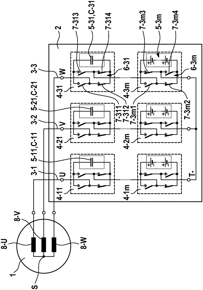
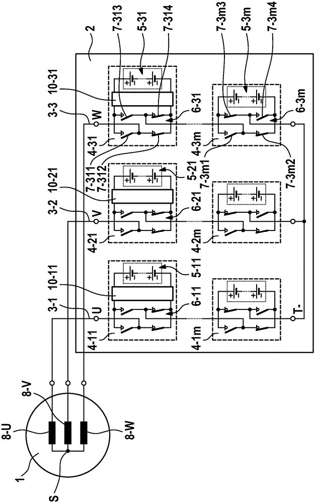
[0026] figure 1 and image 3A schematic diagram of an embodiment of a controllable energy store according to the invention is shown. The controllable energy store 2 is connected to the three-phase electric machine 1 . The controllable energy store 2 comprises three energy supply branches 3 - 1 , 3 - 2 and 3 - 3 , which are connected on the one hand to a reference potential T− (reference busbar), which in the embodiment shown leads to a low potential, while on the other hand are respectively connected to the phases U, V, W of the motor 1 . Each of the energy supply branches 3-1, 3-2 and 3-3 has m energy storage modules 4-11 to 4-1m or 4-21 to 4-2m or 4-31 to 4-3m connected in series , where m≥2. The energy storage modules 4 in turn each comprise a plurality of electrical energy storage cells connected in series, which are only partly assigned the reference numerals 5-11, 5-21 and 5-31 to 5-3m for reasons of clarity . The energy storage modules 4 also each include a coupli...


PUM


Abstract

The invention relates to a controllable energy store (2) having n parallel energy supply branches (3-1, 3-2, 3-3), where n≥1, said energy supply branches each having at least Two series-connected energy storage modules (4), each comprising at least one electrical energy storage unit (5) with an associated controllable coupling unit (6). The coupling unit (6) bridges the respectively allocated energy storage units (5) or connects the respectively allocated energy storage units (5) to corresponding energy supply branches (3-1, 3-2, 3-3). The at least one energy storage module ( 4 - 11 ; 4 - 21 ; 4 - 31 ) is designed in such a way that the at least one energy storage module is connected to the corresponding energy supply branch ( 3 - 1 ; 3 - 2 ; 3 - 3 ) Compared with other energy storage modules (4) in , the switching loss is reduced, especially reduced by at least 10%.

Description

technical field [0001] The invention relates to a controllable energy store and a method for operating a controllable energy store. Background technique [0002] It appears that electronic systems combining new energy storage technologies with electric drive technology will be increasingly used in the future not only in stationary applications such as wind power plants but also in vehicles such as hybrid or electric vehicles. In conventional applications, electric machines, for example embodied as induction motors, are controlled via a converter in the form of an inverter. Typical of such a system is a so-called direct voltage intermediate link via which an energy store (usually a battery) is connected to the direct voltage side of the inverter. In order to be able to meet the power and energy requirements for the respective application, a plurality of battery cells are connected in series. Since the current supplied by such an energy store necessarily flows through all th...

Claims


Application Information

Patent Timeline
Patent Type & Authority Patents(China)
IPC IPC(8): H02J7/00H02M7/44H02J7/14H02M7/483
CPCH02J7/0024H02J7/1492H02M7/483Y02T10/92B60L58/18B60L58/21H02J2207/20H02J2310/48H02J2300/28H02J7/0025Y02T10/70H02M7/4835H02M7/49H02J7/00H02J7/14H02M7/44Y02E10/76H02J1/10
Inventor M·凯斯勒P·福伊尔施塔克E·魏森博恩
Owner ROBERT BOSCH GMBH
Why Eureka
Try Eureka