
Magnetic coupling resonance wireless power supplying device using fundamental wave energy in high-frequency square wave

A magnetic coupling resonance, wireless power supply technology, applied in circuit devices, electrical components, electromagnetic wave systems, etc., can solve the problems of poor consistency of optimal resonance points, device parameter errors, affecting transmission distance, etc., and achieves wide application and simple structure. Effect

Active Publication Date: 2013-08-21
ZONECHARGE (SHENZHEN) WIRELESS POWER TECH CO LTD
View PDF5 Cites 17 Cited by
  • Summary
  • Abstract
  • Description
  • Claims
  • Application Information

AI Technical Summary

Problems solved by technology

[0003] At present, magnetic resonance coupling wireless power supply technology needs to rely on two resonant coils with the same frequency, but in practical applications, due to device parameter errors, it is difficult to achieve two coils with exactly the same resonant parameters, so the frequency points of the two resonant coils are difficult to be completely unanimous
Not only does this affect the transmission distance, but the overall efficiency of the system is also limited due to the presence of multiple coupling coils
Therefore, it is necessary to study high-efficiency working circuits based on magnetically coupled resonance wireless power supply to solve the problem of poor consistency of the optimal resonance point between resonant coils for wireless power supply

Method used


Image

  • Magnetic coupling resonance wireless power supplying device using fundamental wave energy in high-frequency square wave
  • Magnetic coupling resonance wireless power supplying device using fundamental wave energy in high-frequency square wave
  • Magnetic coupling resonance wireless power supplying device using fundamental wave energy in high-frequency square wave

Examples


Embodiment 1

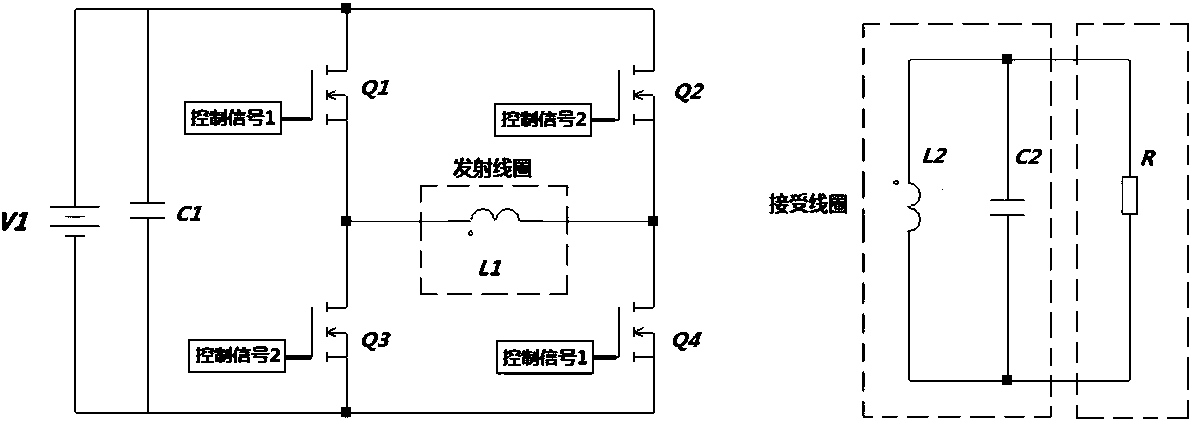
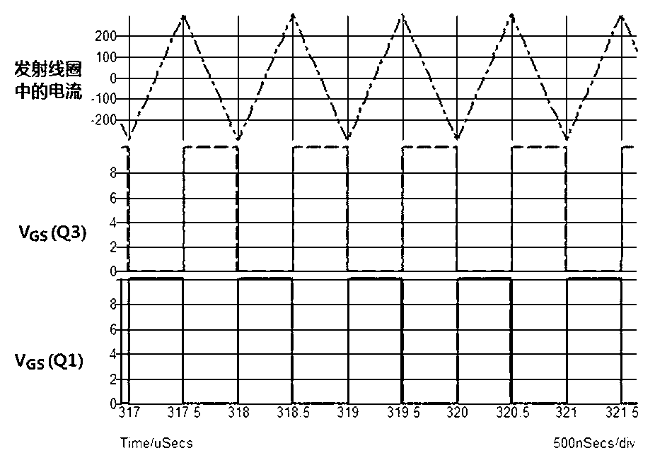
[0023] Such as figure 1 As shown, the transmitting circuit is composed of a DC power supply V1, an input capacitor C1, a full-bridge inverter composed of switching tubes Q1-Q4, and a transmitting coil L1. The receiving circuit includes receiving coil L2, capacitor C2 and load R1. The control circuit generates two control signals for the switch tubes Q1-Q4, wherein the first control signal is for the switch tube Q1 and the switch tube Q4, and the second control signal is for the switch tube Q2 and the switch tube Q3. The first control signal and the second control signal are square wave signals with complementary conduction, and a certain dead zone is left.

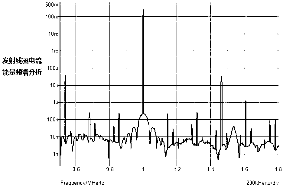
[0024] The control circuit outputs high-frequency signals to the drive circuit, and provides the driving capability required for high-frequency operation for the switch tubes Q1-Q4. At this time, the switching frequency provided by the control circuit to the switch tubes Q1-Q4 is f 1 . The frequency f of the square wave...

Embodiment 2

[0030] Such as Figure 5 As shown, the transmitting circuit is composed of DC power supply V1, freewheeling diodes D1, D2, switching tubes Q1, Q2, and transmitting coil L1. The receiving circuit includes receiving coil L2, capacitor C1 and load R1. The control signal generates a control signal and provides it to the switch tubes Q1 and Q2 at the same time, wherein the maximum duty ratio of the control signal does not exceed 0.5. The control circuit outputs a high-frequency signal to the drive circuit to provide the driving capability required for high-frequency operation for the Q1 and Q2 switch tubes. At this time, the control circuit provides the switch tubes Q1 and Q2 with a switching frequency of f 1 . The frequency f of the square wave driving signal generated by the control circuit is1 and receiving coil inductance L 2 , Resonant capacitance C 1 The resulting resonant frequency same as f 1 =f 2 . Since the frequency of the magnetic field caused by the current in...


PUM


Abstract

The invention discloses a magnetic coupling resonance wireless power supplying device using fundamental wave energy in a high-frequency square wave and belongs to wireless energy transmitting device. The magnetic coupling resonance wireless power supplying device comprises a control circuit, a drive circuit, an emitting circuit and a resonance receiving circuit. The emitting circuit comprises an input power supply and a non-resonance converter connected with the input power supply and comprising an emitting coil. The resonance receiving circuit comprises a receiving coil, a resonance capacitor and a load. The magnetic coupling resonance wireless power supplying device directly controls a square wave voltage frequency of the emitting coil in the non-resonance converter. When the square wave voltage frequency is identical with resonance frequency points of the receiving coil, the magnetic coupling resonance wireless power supplying is achieved. Two coils which share the same resonance point frequency are not needed for achieving resonance working and reliability of a wireless electric energy device is improved. ZVS switching in a total range is easy to achieve. EMI interference is low and an application prospect is wide.

Description

technical field [0001] The invention relates to a wireless energy transmission device, in particular to a wireless power supply device using fundamental wave magnetic coupling resonance, which is used in occasions where wireless energy needs to be supplied. Background technique [0002] As a new type of wireless power supply technology, non-radiative magnetic coupling resonance generates strong mutual coupling between two resonant objects of the same frequency, while only weakly couples to the receiving end of the surrounding non-resonant frequency. The magnetically coupled resonant system includes a transmitting resonant coil, a secondary receiving resonant coil and a load. Assistant Professor Marin Soljacic of MIT is the inventor of the system, and his MIT research group demonstrated wireless power supply. They successfully lit a 60W light bulb from a distance of 2 meters. Magnetic coupling resonance technology can achieve mid-range energy transmission without increasing ...

Claims


Application Information

Patent Timeline
Patent Type & Authority Applications(China)
IPC IPC(8): H02J17/00H02J50/12
Inventor 周岩高飞张腾飞谢俊
Owner ZONECHARGE (SHENZHEN) WIRELESS POWER TECH CO LTD
Learn More