
A kind of manufacturing method of carbon fiber conveying pipe for conveying concrete

A production method and technology for conveying pipelines, which are applied in pipeline protection, pipeline damage/wear prevention, and pipes, etc., can solve problems such as reduced equipment utilization, vehicle instability, and hidden safety hazards, and achieve reduced gravity load and service life. The effect of prolonging, increasing the amount of concrete

Inactive Publication Date: 2015-08-05
CHENGDU XINZHU ROAD & BRIDGE MASCH CO LTD
View PDF9 Cites 1 Cited by
  • Summary
  • Abstract
  • Description
  • Claims
  • Application Information

AI Technical Summary

Problems solved by technology

[0005] First, the service life of the existing concrete delivery pipelines is generally short, which affects the pumping capacity and reduces the utilization rate of equipment;
[0006] Second, the overall quality of the existing concrete delivery pipeline is too heavy. After installation on the boom, the gravity load of the boom will be increased, the fatigue limit of the boom will be reduced, and the vibration amplitude of the boom will be relatively large, resulting in the concrete being in the pumping state. The instability of the car will directly affect the working efficiency of the whole car, and there are also certain hidden dangers in use;
[0007] Third, the existing concrete delivery pipelines have limited pipe diameters, which cannot meet the delivery capacity requirements matching the large bore and large displacement of concrete delivery cylinders, resulting in restrictions on the volume of concrete and directly affecting production efficiency

Method used


Image

  • A kind of manufacturing method of carbon fiber conveying pipe for conveying concrete
  • A kind of manufacturing method of carbon fiber conveying pipe for conveying concrete
  • A kind of manufacturing method of carbon fiber conveying pipe for conveying concrete

Examples


Embodiment Construction

[0015] The present invention will be described in detail below in conjunction with the accompanying drawings and specific embodiments.

[0016] A carbon fiber conveying pipe used for conveying concrete, the content of carbon fiber material in its batching composition is 100%.

[0017] Such as figure 1 As shown, for the standard straight pipe in the carbon fiber delivery pipeline, the pipe wall thickness is more than 4mm, and the pipe wall thickness of the thickened straight pipe is more than 7mm.

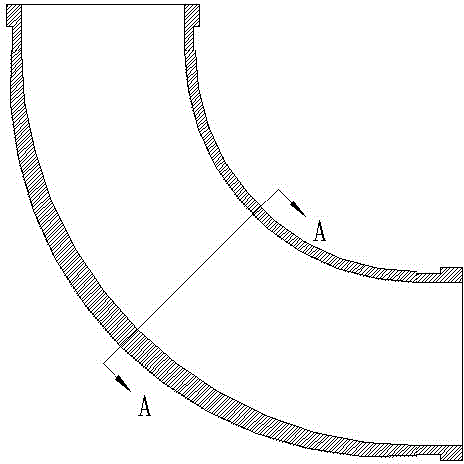
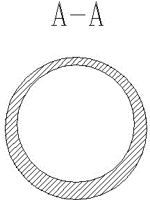
[0018] Such as figure 2 , image 3 As shown, for the elbow in the carbon fiber delivery pipeline, the thickness of the thinnest part of the pipe wall is more than 7 mm, and the thickness of the thickest part of the pipe wall is 2 to 3 times the thickness of the thinnest part of the pipe wall.

[0019] The manufacturing method of a carbon fiber delivery pipeline for transporting concrete mainly includes the following steps: S1. Oxidation treatment to obtain pre-oxidized carbon fi...


PUM

PropertyMeasurementUnit
thicknessaaaaaaaaaa
thicknessaaaaaaaaaa
densityaaaaaaaaaa

Abstract

The invention relates to a carbon fiber delivery pipe for delivering concrete, and a production method thereof. Ingredients of the carbon fiber delivery pipe for delivering the concrete include 100% of carbon fiber materials; pipe wall thickness of a standard straight pipe is more than 4mm, and the pipe wall thickness of a thickened straight pipe is more than 7mm; and the thinnest position of the pipe wall of a bended pipe is more than 7mm, and the thickest position is more than 14mm. The production method of the carbon fiber delivery pipe for delivering the concrete includes S1, performing oxidation treatment to obtain pre-oxidation carbon dioxide; S2, performing carbonization including two sequential stages of high temperature carbonization and low temperature carbonization to obtain graphitized carbon fibers; S3, netting to obtain a piece of carbon fiber clothing; and S4, bonding and shaping to obtain products of carbon fiber pipes. The carbon fiber delivery pipe produced by the method has the advantages of light weight, long service life, small impact, small pressure lose and the like; the diameter of the delivery pipe can be increased, and production efficiency can be improved.

Description

technical field [0001] The invention relates to the technical field of concrete pumping mechanical equipment, in particular to a carbon fiber conveying pipeline for conveying concrete. [0002] The invention also relates to a manufacturing method of the carbon fiber conveying pipe for conveying concrete. Background technique [0003] Concrete pumping mechanical equipment is a large-scale complete set of automatic equipment used to transport fresh concrete in a short distance. It can transport concrete with a slump within a certain range to a certain height or a certain distance horizontally. It is widely used in urban commercial concrete, In the on-site construction of large and medium-sized infrastructure such as railways, roads, bridges, dams, airports, and docks, the concrete delivery pipeline is a key component of the concrete pipeline system in the concrete pumping machinery and equipment. [0004] In the prior art, the existing concrete delivery pipeline mainly has ...

Claims


Application Information

Patent Timeline
Patent Type & Authority Patents(China)
IPC IPC(8): F16L9/16F16L43/00F16L57/06
Inventor 马先志
Owner CHENGDU XINZHU ROAD & BRIDGE MASCH CO LTD
Learn More