
A co-rotating twin-screw transmission device using an oil motor

A transmission device and oil motor technology, applied in transmission devices, transmission device parts, gear transmission devices, etc., can solve the problems of large space occupation and complex structure

Inactive Publication Date: 2016-03-30
SHANXI BEIFANG XINGAN CHEM IND
View PDF6 Cites 0 Cited by
  • Summary
  • Abstract
  • Description
  • Claims
  • Application Information

AI Technical Summary

Problems solved by technology

[0003] The purpose of the present invention is to provide a co-rotating twin-screw drive using an oil motor in order to solve the shortcomings of the electric drive device in the traditional co-rotating parallel twin-screw plasticizing extrusion system. device

Method used


Image

  • A co-rotating twin-screw transmission device using an oil motor
  • A co-rotating twin-screw transmission device using an oil motor
  • A co-rotating twin-screw transmission device using an oil motor

Examples


Embodiment

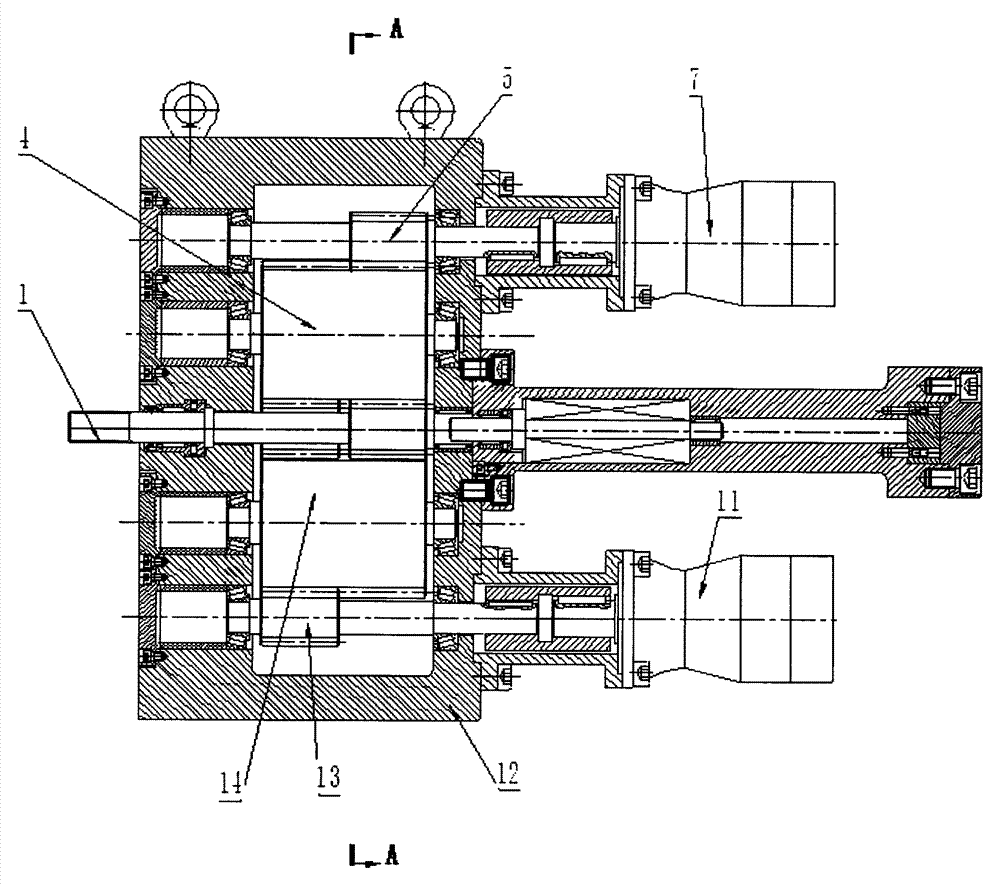
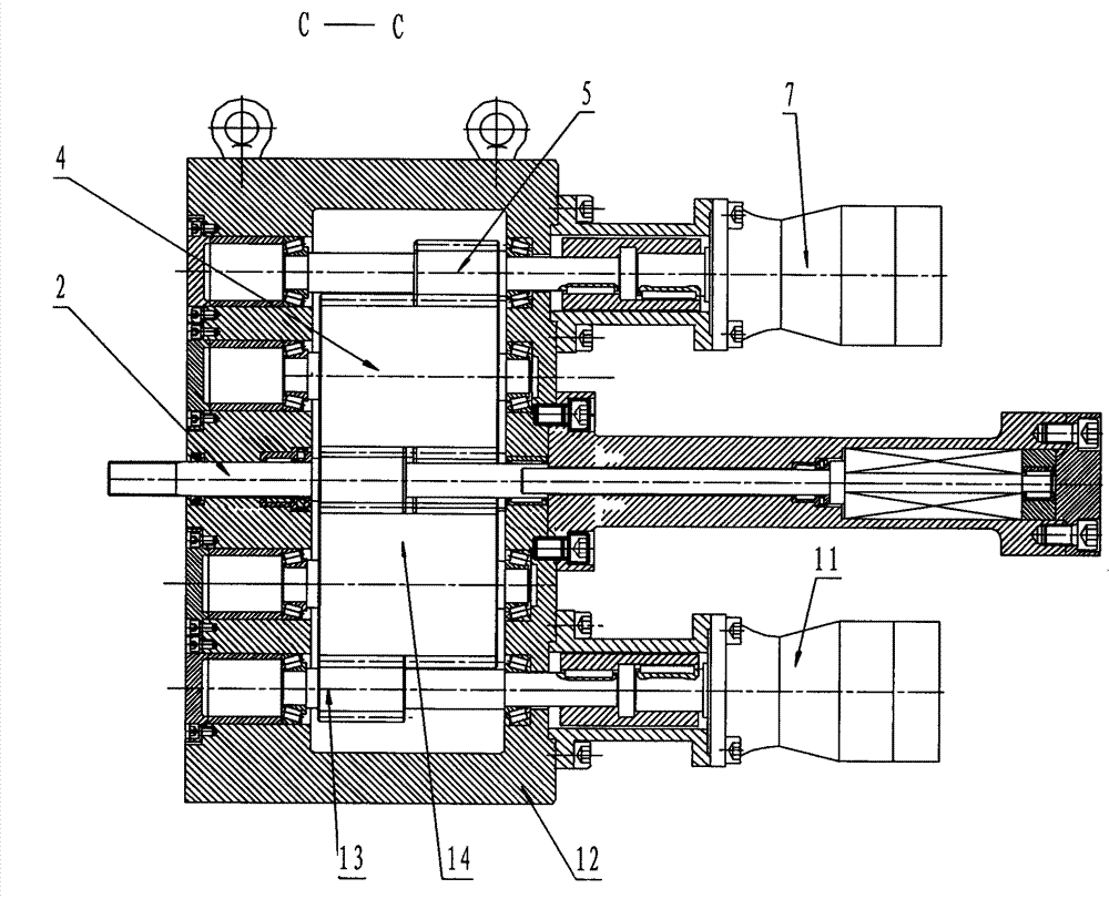
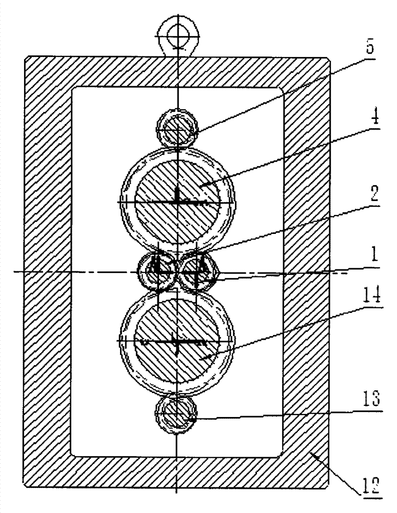
[0019] A kind of co-rotating twin-screw transmission device adopting oil motor of the present invention, such as figure 1 , 2 As shown, including output gear shaft A1, output gear shaft B2, thrust roller bearing, transition gear shaft A4, input gear shaft A5, oil motor bracket, oil motor A7, thrust bearing, coupling, oil motor B11, transmission Case body 12, input gear shaft B13, transition gear shaft B14.

[0020] The output gear shaft A1 and the output gear shaft B2 are horizontally arranged in the center of the transmission box 12 in parallel, and transmission gears are fixed on the output gear shaft A1 and the output gear shaft B2, and the transmission gears on the output gear shaft A1 and the output gear shaft B2 are front and rear Dislocation setting; the rear ends of the output gear shaft A1 and the output gear shaft B2 both pass through the rear end of the transmission box 12, and are respectively connected with a set of thrust bearings, and the two sets of thrust bea...


PUM


Abstract

The invention relates to a co-rotating twin-screw transmission device using an oil motor, which belongs to the field of plasticizing extrusion molding. The two output gear shafts of the present invention are horizontally and parallelly arranged in the center of the transmission box body, and the transmission gears on it are arranged in a front and rear misalignment, and the front ends of the two output gear shafts are used as the drive shafts of the twin screws; Two transition gear shafts are respectively arranged on both sides, and each transition gear shaft is fixed with two front and rear transmission gears. The last two transmission gears of the transition gear shaft are engaged with the transmission gears of the other output gear shaft at the same time; the two input gear shafts drive the two transition gear shafts respectively through the oil motor; the present invention enables the twin screws to rotate in the same direction, In addition, the torque received by the output bearing is greatly improved, and the radial force of the output shaft is balanced.

Description

technical field [0001] The invention relates to a co-rotating twin-screw transmission device using an oil motor, which belongs to the field of plasticizing extrusion molding. Background technique [0002] Usually, in the plasticizing molding process of heat-sensitive materials, the co-rotating parallel twin-screw plasticizing extrusion device is driven by a motor, and the screw is driven to rotate through a reducer and a distribution box. Due to the special requirements of the plasticization molding process of heat-sensitive materials, the screw needs to work at ultra-low speed and ultra-high torque. Restricted by the structural characteristics of the output shaft of the distribution box of the co-rotating parallel twin-screw plasticizing extruder, the axial dimension is very long and the machining accuracy is high. The mechanical transmission requires a huge reduction device and a complicated transmission chain. An oil motor-driven screw device with co-rotating parallel tw...

Claims


Application Information

Patent Timeline
Patent Type & Authority Patents(China)
IPC IPC(8): F16H1/22F16H57/023B29C47/58B29C47/40B29C48/405B29C48/50
CPCB29C48/435B29C48/405
Inventor 郑建利阎斌崔敬学张宏革张秀娥张斌贾新娟
Owner SHANXI BEIFANG XINGAN CHEM IND
Learn More