Upward-flowing fluidization biofilter coupled with negative pressure membrane

A biological filter, negative pressure membrane technology, applied in biological water/sewage treatment, chemical instruments and methods, water/sludge/sewage treatment, etc. The effect of biomass, power consumption reduction, and biological loss reduction

Active Publication Date: 2013-08-21
HARBIN INST OF TECH
View PDF2 Cites 4 Cited by
  • Summary
  • Abstract
  • Description
  • Claims
  • Application Information

AI Technical Summary

Problems solved by technology

[0006] The purpose of the present invention is to solve the technical problem that the existing biological filter has poor filtering effect on suspended particles, plankton, benthic animals and microbial residues in the water body, and the turbidity of the effluent is high, and provides a kind of filter with negative pressure membrane Coupled upflow fluidized biological filter and its water treatment method

Method used


Image

  • Upward-flowing fluidization biofilter coupled with negative pressure membrane
  • Upward-flowing fluidization biofilter coupled with negative pressure membrane
  • Upward-flowing fluidization biofilter coupled with negative pressure membrane

Examples


specific Embodiment approach 1

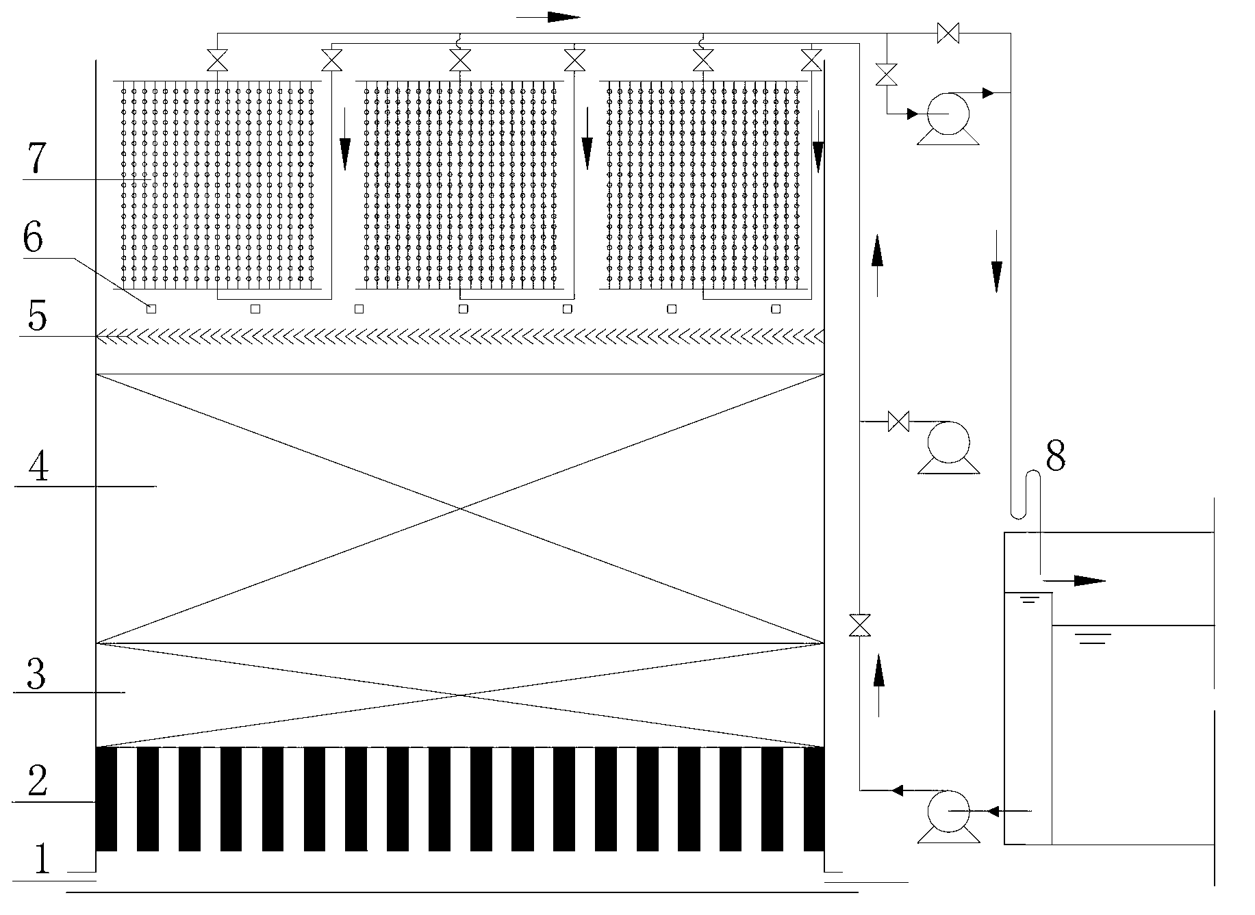
[0026] Specific embodiment 1: In this embodiment, an upflow fluidized biological filter coupled with a negative pressure membrane includes a water inlet 1, a water distribution layer 2, a supporting layer 3, a packing layer 4, and an anti-disturbance inclined plate 5 , air flotation release device 6 and negative pressure membrane assembly 7, it is characterized in that:

[0027] The negative pressure membrane assembly 7 is completely submerged in the clear water area on the upper part of the filling layer 4 in the upward flow fluidized biological filter coupled with the negative pressure membrane;

[0028] The anti-disturbance sloping plate 5 is located between the biofilter packing layer 4 and the negative pressure membrane assembly 7;

[0029] The air flotation releaser 6 is located at the bottom of the negative pressure membrane assembly 7;

[0030] The top wall of the upward flow fluidized biological filter coupled with the negative pressure membrane is provided with a fl...

specific Embodiment approach 2

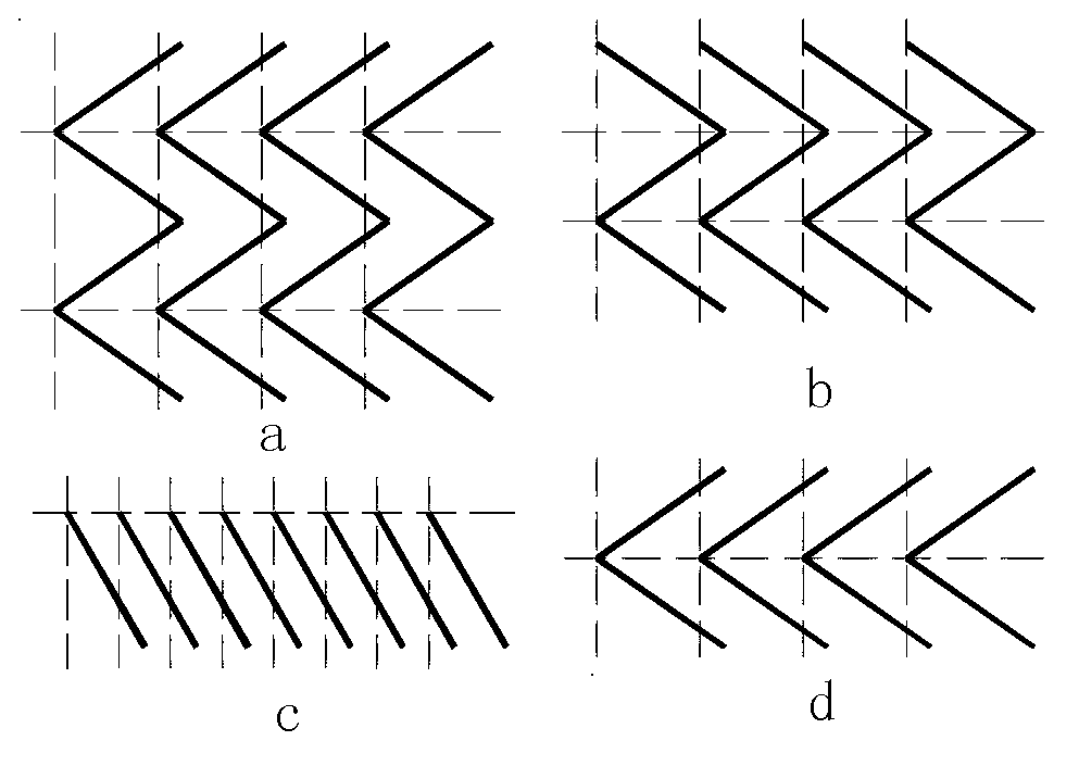
[0031] Embodiment 2: The difference between this embodiment and Embodiment 1 is that the anti-disturbance swash plate 5 is composed of a series of "V" or "W" components rotated by 90 degrees. Others are the same as in the first embodiment.

specific Embodiment approach 3

[0032] Embodiment 3: The difference between this embodiment and Embodiment 1 or 2 is that the single component of the anti-disturbance swash plate 5 is composed of two or several long-strip plates connected in sequence by the long sides, and the clamping The angle is between 30 degrees and 90 degrees. Others are different from the first or second specific embodiment.


PUM

PropertyMeasurementUnit
angleaaaaaaaaaa
particle diameteraaaaaaaaaa
thicknessaaaaaaaaaa

Abstract

The invention relates to a biofilter and discloses an upward-flowing fluidization biofilter coupled with a negative pressure membrane, for solving the technical problems of an existing biofilter, such as poor filtering effect on suspended particles, planktons, benthonic animals and microorganism residues in water bodies, as well as high turbidity of treated water. The upward-flowing fluidization biofilter comprises a water inlet, a water distribution layer, a supporting layer, a filling layer, an anti-interference cantboard, an air floatation releaser and a negative pressure membrane assembly. According to a water treatment process, inlet water passes through the upward-flowing biofilter, is filtered by the negative pressure membrane in an upper clear water area and is naturally siphoned by using a siphon tube to discharge water, and thus a water treatment process is finished. The method can be used for effectively removing organic pollutants, natural organic matters, ammonia nitrogen and other pollutants out of water, the loss of biological matters is reduced, a wear damage effect of particles, such as filler, on membranes is avoided, and the plugging effect of biological metabolites and biological cells on the membranes is also avoided.

Description

technical field [0001] The invention relates to a biofilter. Background technique [0002] In recent years, with the extensive use of chemical fertilizers, pesticides, herbicides, etc., the pollution of surface water has become increasingly serious. Ammonia nitrogen, organic micro-pollutants such as pesticides, odorous substances, etc. have become important pollutants in water sources. Therefore, removing water Ammonia nitrogen, organic micro-pollutants, etc. have become urgent problems for water supply plants. Traditional coagulation, sedimentation, and filtration processes have low removal rates for ammonia nitrogen and trace organic matter, and it is difficult for the treated effluent to meet the relevant national standards for drinking water quality. At the same time, the contradiction between people and land in cities is increasing day by day, and the renovation and upgrading of old plants and the construction of new water plants are facing the problem of rising land c...

Claims


Application Information

Patent Timeline
Patent Type & Authority Applications(China)
IPC IPC(8): C02F3/00
Inventor 马军杨家轩翟学东时玉龙
Owner HARBIN INST OF TECH
Why Eureka
Try Eureka