Lens mirror frame and lens assembly

A lens and frame technology, applied in installation, instruments, optics, etc., can solve problems such as easy to cause eccentricity, and achieve the effect of good balance and high-precision fixation

Inactive Publication Date: 2013-08-14
OLYMPUS CORP
View PDF8 Cites 3 Cited by
  • Summary
  • Abstract
  • Description
  • Claims
  • Application Information

AI Technical Summary

Problems solved by technology

However, with this structure, the lens tends to move to the side without the caulking portion due to the pressing force acting through the caulking portion during thermal caulking, which tends to cause eccentricity.

Method used


Image

  • Lens mirror frame and lens assembly
  • Lens mirror frame and lens assembly
  • Lens mirror frame and lens assembly

Examples


Embodiment Construction

[0064] The lens frame and lens assembly according to the embodiment of the present invention will be described.

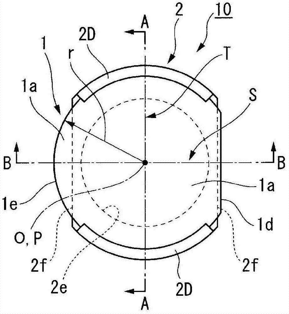
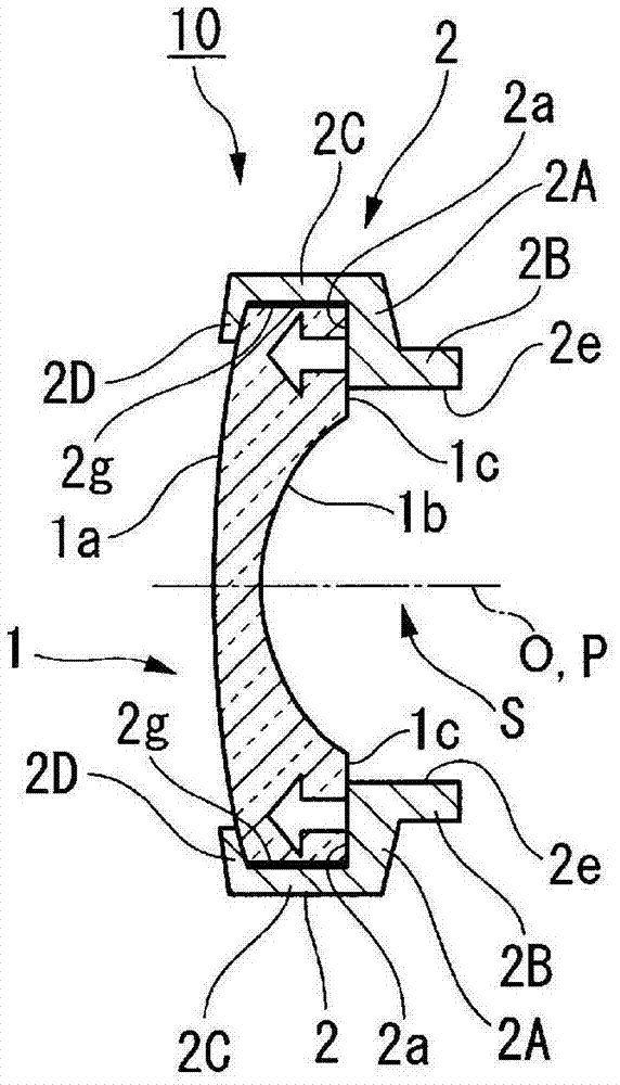
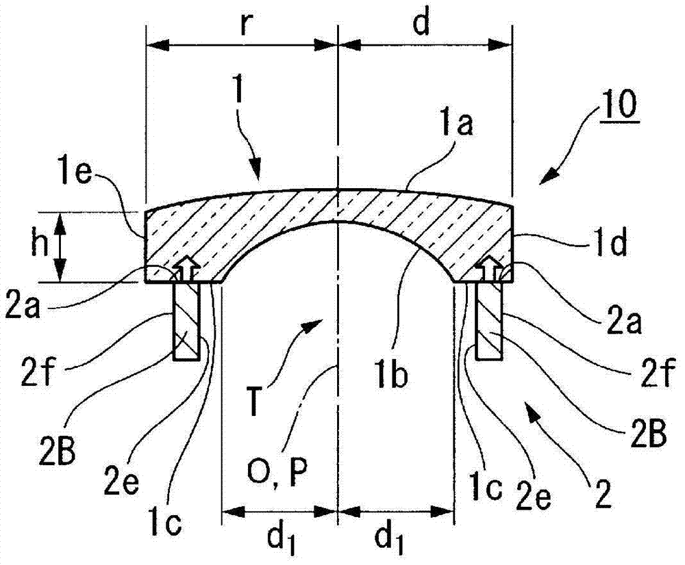
[0065] Figure 1A It is a schematic plan view showing the structure of the lens assembly according to the embodiment of the present invention. Figure 1B , Figure 1C respectively Figure 1A A-A sectional view, B-B sectional view in the. Figure 2A It is a schematic plan view which shows the structure of the lens frame which concerns on embodiment of this invention. Figure 2B , Figure 2C respectively Figure 2A A'-A' section view, B'-B' section view in the.

[0066] Such as Figure 1A , Figure 1B , Figure 1C As shown, the lens assembly 10 of this embodiment is an assembly formed by heat caulking the lens 1 in the thickness direction on the outer edge of the lens 1 and fixing it to the lens frame 2. The lens 1 The outer shape viewed from the direction along the optical axis is formed of a circular arc shape and a straight line shape. The caulking fixi...


PUM


Abstract

This lens mirror frame comprises: a lens-receiving surface extending in an intersection direction intersecting a central axis; a side frame part projecting from the lens-receiving surface in the direction of the central axis, the side frame part arranged further outward than the lens-receiving surface in the intersection direction; and a plurality of crimp parts deformed by external pressure to securely crimp a lens within a space bounded by the lens-receiving surface. The lens-receiving surface is formed so as to be axially symmetric to the central axis.

Description

technical field [0001] The invention relates to a lens frame and a lens assembly. [0002] This application claims priority based on Japanese Patent Application No. 2011-035755 filed in Japan on February 22, 2011, the contents of which are incorporated herein. Background technique [0003] Conventionally, for example, optical devices such as cameras use lens assemblies in which optical elements such as lenses are fixed to lens frames made of thermoplastic resin by heat caulking. [0004] For example, Patent Document 1 describes, as such a lens frame, a lens frame formed of a plastic material into a substantially cylindrical shape and having a lens insertion frame portion and a caulking portion. The lens insertion frame portion is formed in a concave shape at one end opening of a substantially cylindrical shape constituting the lens frame, and the lens is inserted into the end opening to position the lens in the optical axis direction. Each of the four caulking portions pro...

Claims


Application Information

Patent Timeline
Patent Type & Authority Applications(China)
IPC IPC(8): G02B7/02
CPCG02B7/022G02B7/026
Inventor 水月直树山崎仁岩濑充洋
Owner OLYMPUS CORP
Why Eureka
Try Eureka