Clamp for fixing magnetic head assembly and measuring method of rising quantity using the same

An assembly and fixture technology, which is applied to the functional test of the magnetic head, the hydrodynamic spacing of the head, the configuration/installation of the recording head, etc., can solve the problems of the inability to locate the slider and the complicated positioning of the magnetic head assembly 503, etc. Achieve the effect of high-precision measurement

Inactive Publication Date: 2007-03-28
TDK CORPARATION
View PDF1 Cites 0 Cited by
  • Summary
  • Abstract
  • Description
  • Claims
  • Application Information

AI Technical Summary

Problems solved by technology

[0008] Because the support table 501 that is arranged on the conventional magnetic head detector 500 shown in Figure 10 is after making a pair of positioning pins 506a, 506b pass through the holes 505c, 505d of the rectangular member 505, because the fixing member 504 is positioned at a 45-degree angle direction The parts of the magnetic head assembly are moved obliquely and positioned, so the positioning operation of the magnetic head assembly 503 will be complicated.
In addition, since the surface of the rectangular member 505 is not pressed against the support table 501, the slider cannot be positioned in three-dimensional directions with high precision.

Method used


Image

  • Clamp for fixing magnetic head assembly and measuring method of rising quantity using the same
  • Clamp for fixing magnetic head assembly and measuring method of rising quantity using the same
  • Clamp for fixing magnetic head assembly and measuring method of rising quantity using the same

Examples


Embodiment Construction

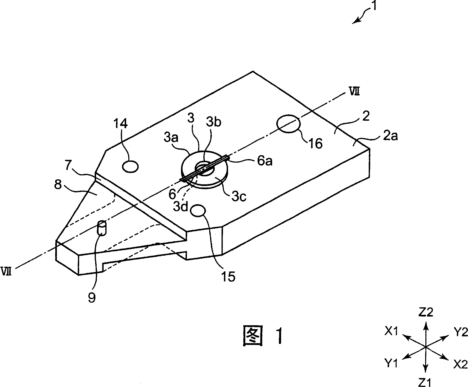
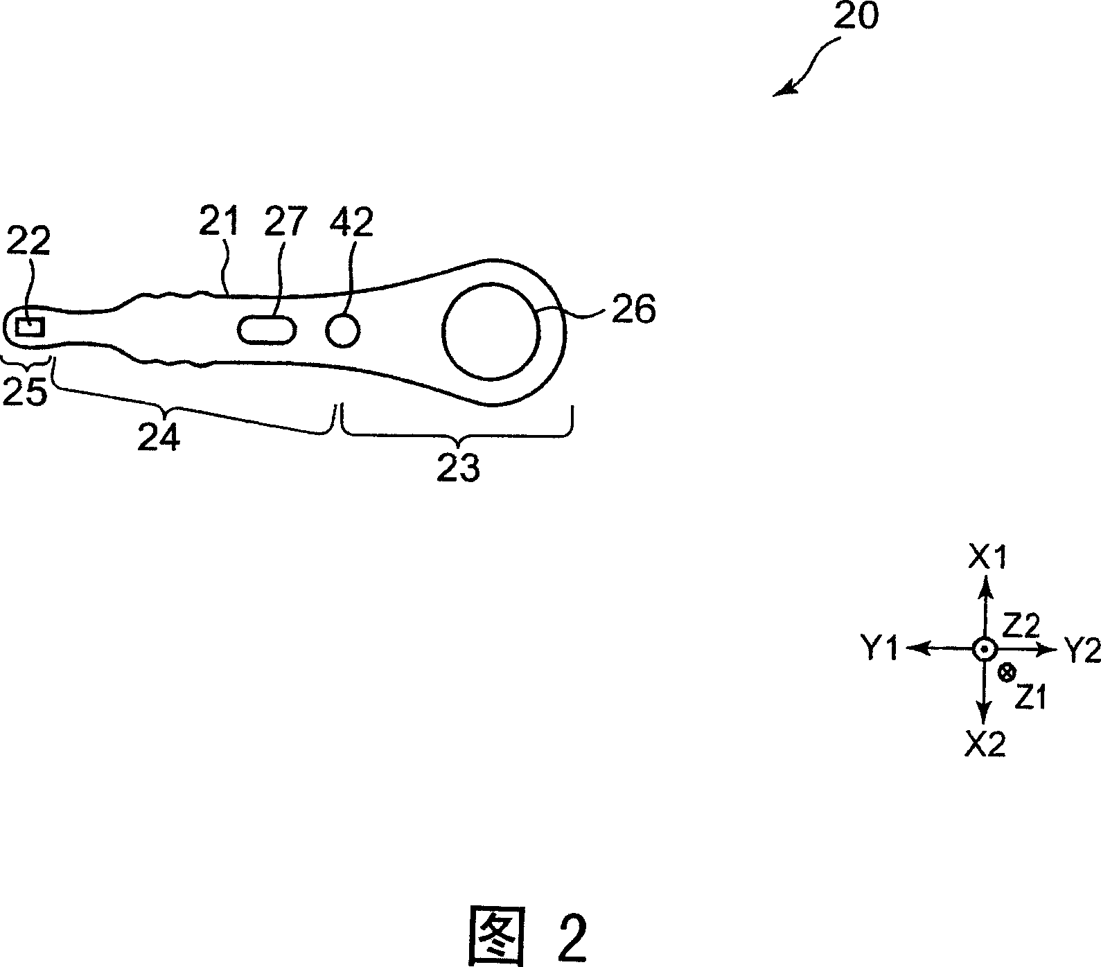
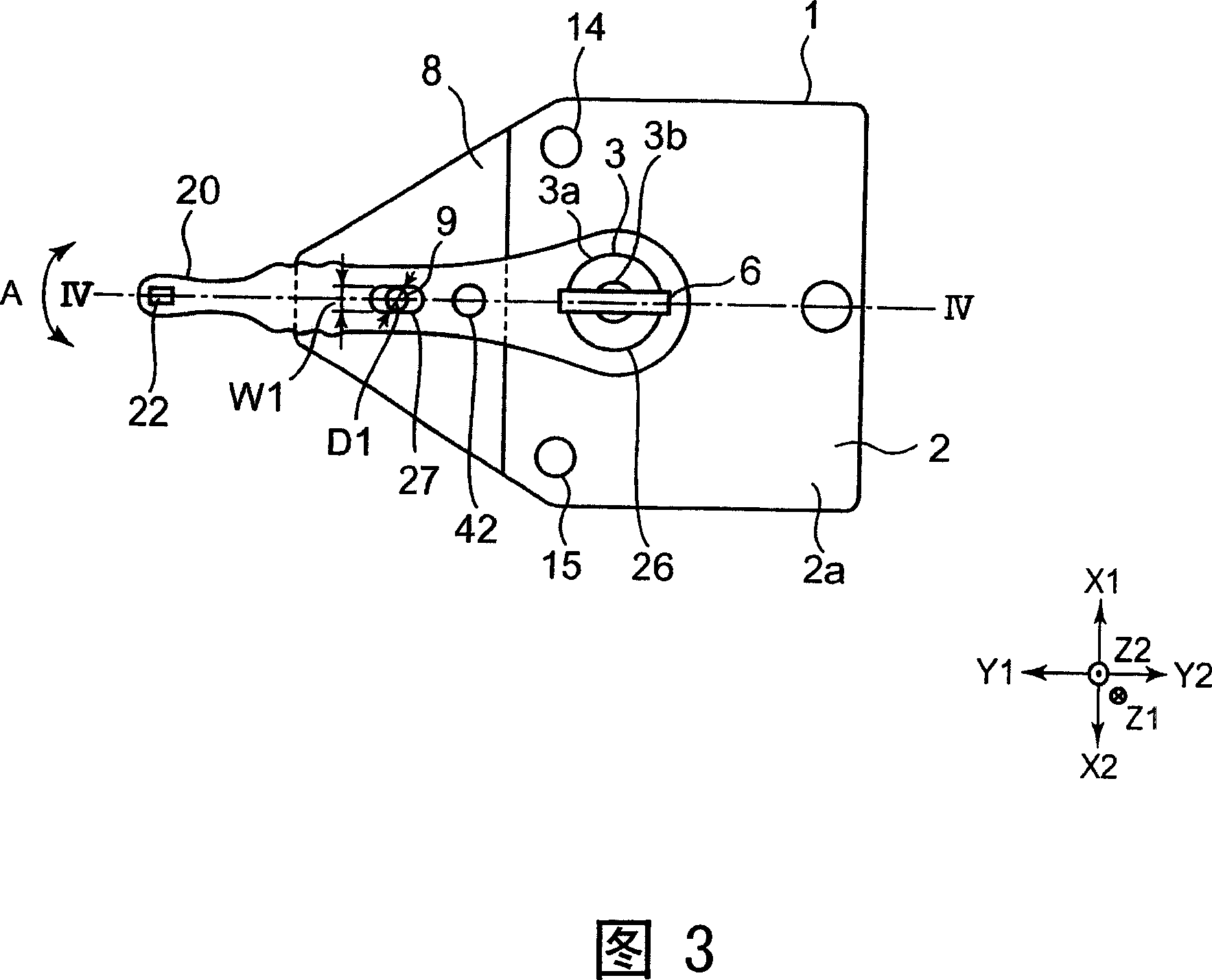
[0052] 1 is a perspective view showing a first embodiment of a fixing jig used when measuring the floating amount of the magnetic head assembly of the present invention from the upper side, and FIG. 2 is a perspective view showing the fixing jig engaged in FIG. A plan view of the magnetic head assembly at the jig, FIG. 3 is a plan view showing a state in which the magnetic head assembly shown in FIG. 2 is fixed at the fixing jig shown in FIG. 1 , and FIG. 4 is cut along line IV-IV of FIG. 3 It cuts the sectional view, and is a schematic diagram of cutting the axis center of the glass disk used in use and the axis of the fixed glass disk rotation drive on the extension line of the above-mentioned IV-IV line.

[0053] The fixing jig 1 shown in FIG. 1 is a magnetic head assembly to which a slider (slider) is fixedly installed. The jig used to measure the floating amount of the head floating from the glass disk is a fixing jig for fixing the magnetic head assembly.

[0054] As sh...


PUM


Abstract

Provided is a fixing tool by which a magnetic head assembly can correctly positioned and held, and the magnetic head assembly can be easily attached and detached, and also provided is a floating height measuring method which can highly precisely measure the floating height of a slider of the magnetic head assembly from a disk surface for measurement. The fixing tool of the invention comprises a base (2) with an installation flat surface (2a), a positioning part (3) for positioning a support plate (21) made to project from the installation flat surface (2a), and a pressure member (6) for fixing the support plate (21) from the installation flat surface (2a). When the support plate (21) is installed on the installation flat surface (2a), the positioning part (3) comes into a support hole (26) to position the support plate (21) from the inside of the support hole (26) in the two directions at right angles to each other along the installation flat surface (2a), and the pressure member (6) is energized on the installation flat surface (2a) by force of a spring (13), and the supporting plate (21) positioned by the positioning part (3) is pressurized on the installation flat surface (2a) by the pressure member (6).

Description

technical field [0001] The present invention relates to a fixing jig for positioning and fixing a magnetic head assembly mounted with a slider on the front portion of a support plate, and a method for measuring the slider from the surface of a magnetic disk for measurement using the above fixing jig. The floating amount measurement method of the floating amount of the head. Background technique [0002] Patent Document 1 shown below discloses a magnetic head detector for measuring the floating amount of a magnetic head assembly mounted with a slider. [0003] FIG. 10 is a plan view showing a positioning portion of the magnetic head assembly disclosed in Patent Document 1 above. [0004] In the magnetic head tester 500 shown in FIG. 10 , a magnetic head assembly 503 on which a slider 502 is mounted is provided on a support table 501 . On the surface of the supporting table 501, a fixing member 504 having inner surfaces 504a and 504b perpendicular to each other is provided. ...

Claims


Application Information

Patent Timeline
Patent Type & Authority Applications(China)
IPC IPC(8): G11B5/455G11B5/48G11B5/60G11B21/21
Inventor 小熊秀和
Owner TDK CORPARATION
Why Eureka
Try Eureka