Local ending point-based numerical control system speed controlling method

A technology of numerical control system and speed control, applied in the direction of digital control, electrical program control, etc., can solve the problems of reducing the frequency of acceleration and deceleration of the system, and achieve the effect of improving production efficiency

Inactive Publication Date: 2015-06-03
NANJING TECH UNIV +3
View PDF7 Cites 0 Cited by
  • Summary
  • Abstract
  • Description
  • Claims
  • Application Information

AI Technical Summary

Problems solved by technology

[0004] In view of the existing defects, the purpose of the present invention is to solve the problem that the line segment planned each time in the speed planning process is a separate segment, the acceleration and deceleration profile is required to be an analytical function, the acceleration and deceleration process is symmetrical, and the speed shape is fixed after planning. A numerical control system speed control method based on a local end point, which uses several small straight line segments in the same acceleration segment or deceleration segment as a path unit for a speed planning, which greatly reduces the acceleration and deceleration frequency of the system, reduces the vibration of the system, and improves System operating efficiency

Method used


Image

  • Local ending point-based numerical control system speed controlling method
  • Local ending point-based numerical control system speed controlling method
  • Local ending point-based numerical control system speed controlling method

Examples


Embodiment Construction

[0017] In order to make the object, technical solution and advantages of the present invention clearer, the present invention will be further described in detail below in conjunction with the accompanying drawings and embodiments. It should be understood that the specific embodiments described here are only used to explain the present invention, not to limit the present invention.

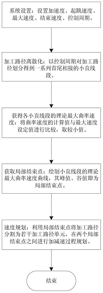
[0018] Such as figure 1 As shown, the flow chart of the speed control method of the numerical control system of the present invention. The speed control method of the numerical control system based on the local end point in this embodiment includes the following steps:

[0019] S1. System settings - set the acceleration of the CNC system = 1200mm / s 2 , take-off speed = 0mm / s, maximum speed V m =1300mm / s, end speed=0mm / s, control period T=0.5ms.

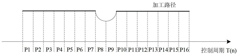
[0020] S2. Discretization of the processing path—assuming that the CNC system runs at the maximum speed V on the processing path m movement, the proc...


PUM


Abstract

The invention relates to a local ending point-based numerical control system speed controlling method, which comprises the steps of drawing a maximum speed curve by obtaining theoretical maximum speeds of all small line sections through computing, selecting a local ending point accordingly, sectioning the processing path by the local ending point, and performing a speed increasing or reducing plan on the sectioned path unit by a system. The method disclosed by the invention plans related continuous multiple sections of small line sections instead of a single small line section every time, thus avoiding frequent speed increasing and reducing, preventing easy generating of relatively large vibrating of a lathe and improving the machining efficiency; and after the method is used for planning the speed, speed increasing and reducing profiles can be sectional or a certain table instead of being analytic functions, and symmetrical speed increasing and reducing processes are not needed.

Description

technical field [0001] The invention relates to a speed control method of a numerical control system based on a local end point, and belongs to the technical field of speed control of a numerical control system. Background technique [0002] CAD / CAM systems often use small straight segments instead of curves to achieve trajectory fitting. Each small segment of trajectory is usually composed of three parts: acceleration process, uniform motion, and deceleration stop. This will cause frequent acceleration and deceleration of the motor, making the machine tool prone to serious problems. Large vibration reduces processing efficiency. [0003] The focus of machining path speed planning is to require the machine tool to move along a given trajectory, while the speed has a certain form of envelope. For example: trapezoidal, S-shaped, exponential, etc., but also to meet the constraints of the maximum speed and acceleration. Trapezoidal and S-shaped curve algorithms can only be app...

Claims


Application Information

Patent Timeline
Patent Type & Authority Patents(China)
IPC IPC(8): G05B19/416
Inventor 舒志兵李泽仁吴晨军高军虎李德亮
Owner NANJING TECH UNIV
Why Eureka
Try Eureka