
Parallel-serial type drying and heating system

A drying heating and hybrid technology, applied in drying, drying machines, heating devices, etc., can solve the problems of long heating time and waste of energy consumption, and achieve the goal of reducing heating time, energy consumption and pressure. effect of demand

Active Publication Date: 2014-11-05
JIANGSU PIAOMA INTELLIGENT EQUIP
View PDF7 Cites 2 Cited by
  • Summary
  • Abstract
  • Description
  • Claims
  • Application Information

AI Technical Summary

Problems solved by technology

[0002] As we all know, in the automobile painting workshop, the structure of the hot air circulation system in the drying room is currently used. The high-temperature flue gas is sent to several heat exchangers connected in series by the heating incinerator through the pipeline. The resistance of the heater, so the resistance that the flue gas needs to overcome is the sum of the resistance of several heat exchangers and pipes. In addition, during the start-up process of the cold furnace, the traditional heating time of the drying room is relatively long. Since this equipment is long-term operation, Therefore energy waste is long-term

Method used


Image

  • Parallel-serial type drying and heating system
  • Parallel-serial type drying and heating system
  • Parallel-serial type drying and heating system

Examples


Embodiment Construction

[0010] The specific implementation manners of the present invention will be further described in detail below in conjunction with the accompanying drawings and embodiments. The following examples are used to illustrate the present invention, but are not intended to limit the scope of the present invention.

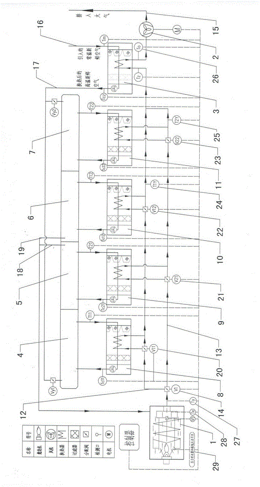
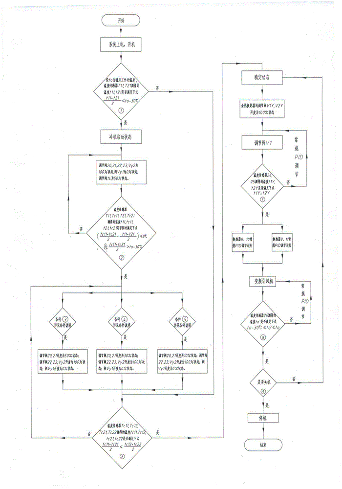
[0011] Such as figure 1 and figure 2 As shown, the hybrid drying heating system of the present invention includes a drying chamber body, a heating incinerator 1, a heat exchanger group, an induced draft fan 2 and a waste heat exchanger 3, and the drying chamber body includes a drying chamber temperature rise Zone 1 4. Drying chamber heating zone 2 5. Drying chamber heat preservation zone 1 6. Drying chamber heat preservation zone 2 7. The heat exchanger group includes the first heat exchanger 8, the second heat exchanger 9, and the third heat exchanger The heat exchanger 10 and the fourth heat exchanger 11, the first heat exchanger is connected in series with the third ...


PUM


Abstract

The invention relates to the technical field of a heating system or device, particularly to a parallel-serial type drying and heating system. According to the parallel-serial type drying and heating system, the resistance of a heat exchanger system is reduced, the demands for pressure of a flue gas induced draft fan are reduced, the energy is reasonably distributed, the heating up time for starting of a black furnace of a drying room is reduced, and the energy consumption is reduced. The parallel-serial type drying and heating system comprises a drying room body, a heating combustion furnace, a heat exchanger group, an induced draft fan and a waste heat exchanger, wherein the drying room body comprises a drying room first heating area, a drying room second heating area, a drying room first heat preservation area and a drying room second heat preservation area; the heat exchanger group comprises a first heat exchanger, a second heat exchanger, a third heat exchanger and a fourth heat exchanger; the heating combustion furnace is communicated with the first heat exchanger and the third heat exchanger through a first communicating pipe; the heating combustion furnace is communicated with the second heat exchanger and the fourth heat exchanger through a second communicating pipe; an air inlet end of the first communicating pipe is communicated with an air inlet end of the second communicating pipe; and a communicating position of the air inlet ends is provided with a distribution valve.

Description

technical field [0001] The present invention relates to the technical field of heating systems or devices, in particular to a hybrid drying and heating system. Background technique [0002] As we all know, in the automobile painting workshop, the structure of the hot air circulation system in the drying room is currently used. The high-temperature flue gas is sent to several heat exchangers connected in series by the heating incinerator through the pipeline. The resistance of the heater, so the resistance that the flue gas needs to overcome is the sum of the resistance of several heat exchangers and pipes. In addition, during the start-up process of the cold furnace, the traditional heating time of the drying room is relatively long. Since this equipment is long-term operation, Therefore, energy waste is long-term. Contents of the invention [0003] In order to solve the above-mentioned technical problems, the present invention provides a heat exchanger system with reduce...

Claims


Application Information

Patent Timeline
Patent Type & Authority Patents(China)
IPC IPC(8): F26B23/02
CPCY02P70/10
Inventor 吉达林徐雷
Owner JIANGSU PIAOMA INTELLIGENT EQUIP
Learn More