
Expansion valve

A technology of expansion valve and valve shell, applied in the field of expansion valve, can solve the problems of pressure loss, difficult expansion valve flow control, etc., and achieve the effect of reliable spot welding and light weight

Active Publication Date: 2013-08-14
SAGINOMIYA SEISAKUSHO INC
View PDF9 Cites 10 Cited by
  • Summary
  • Abstract
  • Description
  • Claims
  • Application Information

AI Technical Summary

Problems solved by technology

Therefore, there is a problem that pressure loss tends to occur in the expanding refrigerant, and it is difficult to control the flow rate of the expansion valve.

Method used


Image

  • Expansion valve
  • Expansion valve
  • Expansion valve

Examples


Embodiment Construction

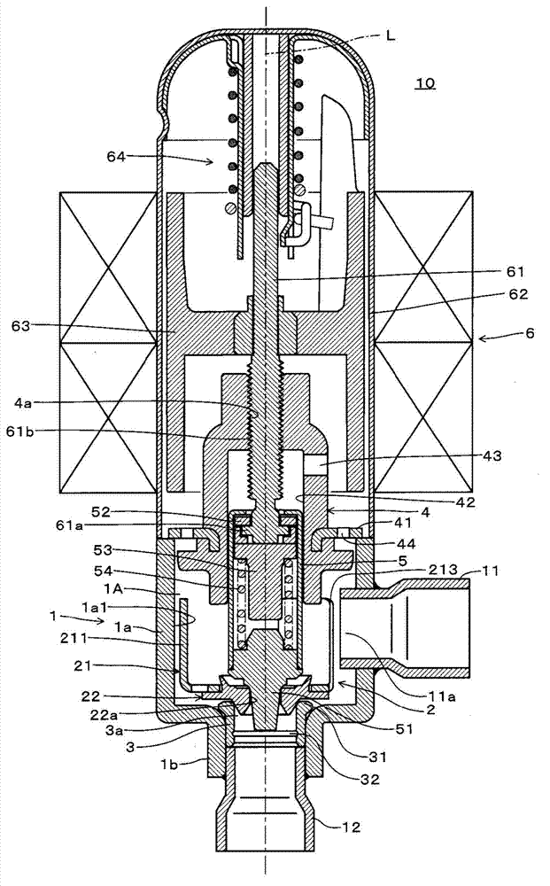
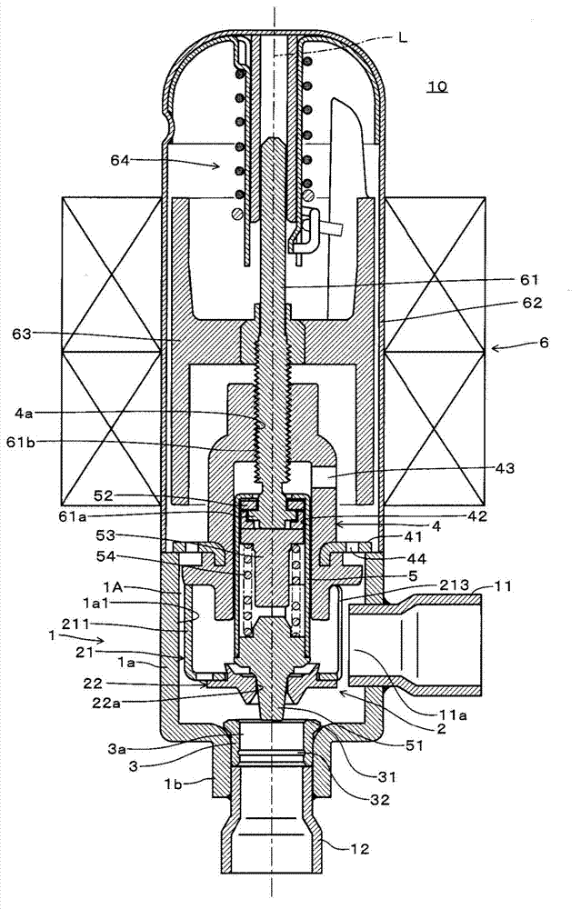
[0034] Embodiments of the expansion valve of the present invention will be described below with reference to the drawings. Figure 7 is a diagram showing a heat pump refrigeration cycle provided with an expansion valve according to an embodiment. First, based on Figure 7 The heat pump refrigeration cycle according to the embodiment will be described. exist Figure 7 in, symbol 10 1 、10 2 are the first expansion valve and the second expansion valve according to the embodiment of the present invention, and the first expansion valve 10 1 Mounted on the outdoor unit 100, the second expansion valve 10 2 It is installed in the indoor unit 200 . expansion valve 10 1 、10 2 , the outdoor heat exchanger 20 , the indoor heat exchanger 30 , the channel switching valve 40 and the compressor 50 are respectively connected as shown in the figure through conduits to form a heat pump refrigeration cycle.

[0035] The flow path of the refrigeration cycle is switched to two flow paths of...


PUM


Abstract

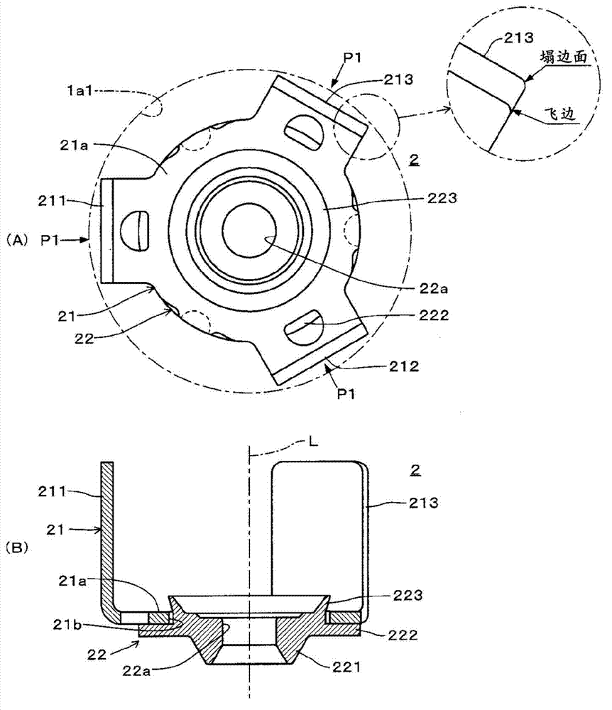
There is provided an expansion valve which, by moving the sub-valve in a valve housing, controls the flow rate of a refrigerant in a first flow direction and releases the refrigerant to flow in a second flow direction, wherein the sub-valve is reduced in weight and a valve port is provided with high accuracy. The sub-valve includes a guide member formed by press work and a valve seat member formed by cutting. The sub-valve is seated on a sub-valve seat of a valve seat ring when the pressure in a main valve chamber is high, and is moved away from the sub-valve seat when the pressure in the main valve chamber is low. The sub-valve is reduced in weight by forming the guide member by press work, and the valve port is formed with improved accuracy by forming the valve seat member by cutting.

Description

technical field [0001] The invention relates to an expansion valve, which is arranged in a heat pump refrigeration cycle, and has the function of throttling the refrigerant relative to the first flow direction of the refrigerant, and minimizes the pressure loss to allow a large flow to flow through. Background technique [0002] Conventionally, in most heat pump refrigeration cycles, an expansion valve is provided on the outdoor heat exchanger side (outdoor unit). In this case, the refrigerant expanded by the expansion valve flows into the indoor heat exchanger through a long pipe. Therefore, there is a problem that pressure loss tends to occur in the expanding refrigerant, and it is difficult to control the flow rate of the expansion valve. Such problems are also the same when the expansion valve is provided on the indoor heat exchanger side. [0003] In response to this, Japanese Unexamined Patent Application Publication No. 2009-287913 (Patent Document 1) proposes an exp...

Claims


Application Information

Patent Timeline
Patent Type & Authority Applications(China)
IPC IPC(8): F25B41/06F25B41/31
CPCF25B2341/061F25B41/062F16K31/04F25B41/043F16K31/0655F25B2341/0653Y02B30/72Y02B30/70F25B41/38F25B41/35F25B41/34
Inventor 关口英树
Owner SAGINOMIYA SEISAKUSHO INC
Learn More