Heat radiator of lamp

A radiator and lamp technology, which is applied to the cooling/heating device of lighting device, lighting and heating equipment, lighting device, etc., can solve the problems of affecting heat dissipation efficiency, poor air circulation and heat dissipation efficiency, affecting the service life of lamps, etc. Achieve the effect of prolonging the service life, improving the air circulation effect and heat dissipation effect, and the air circulation effect and heat dissipation effect.

Inactive Publication Date: 2013-08-14
SUNONWEALTH ELECTRIC MACHINE IND
View PDF6 Cites 8 Cited by
  • Summary
  • Abstract
  • Description
  • Claims
  • Application Information

AI Technical Summary

Problems solved by technology

[0005] However, each of the air holes 912 used to suck air in this existing structure is also located above the lamp, so that the hot air discharged from each of the through holes 921 will also rise and be sucked again through each of the air holes 912. , affecting the cooling performance
And when the existing structure is embedded and hidden, although the penetration holes 921 are exposed on the ceiling surface, the ventilation holes 912 are still buried above the ceiling, so there are still poor air circulation and heat dissipation performances. Then generate heat accumulation and affect the service life of the lamp

Method used


Image

  • Heat radiator of lamp
  • Heat radiator of lamp
  • Heat radiator of lamp

Examples


Embodiment Construction

[0042] In order to make the above-mentioned and other objects, features and advantages of the present invention more obvious and easy to understand, the preferred embodiments of the present invention are exemplified below, and are described in detail as follows in conjunction with the accompanying drawings:

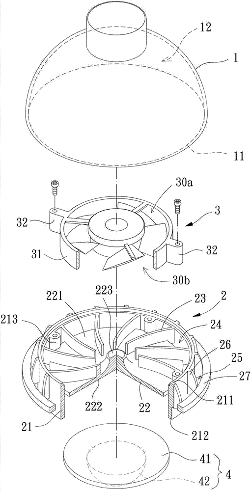
[0043] Please refer to image 3 As shown, it is a lamp according to the first embodiment of the present invention, and the lamp includes a cover 1 , a heat sink 2 , a fan 3 and a light-emitting element 4 . The radiator 2 is arranged between the fan 3 and the light-emitting element 4, and the cover 1 is arranged outside the radiator 2. Therefore, when the fan 3 is running, air can be forced to be sucked in and blown out through the radiator 2. , so that the air in the housing 1 can circulate with the outside, so as to dissipate the heat energy generated by the light-emitting element 4 .

[0044] One end of the outer cover 1 has an opening 11 , and a chamber 12 is recessed...


PUM


Abstract

A heat radiator of a lamp is provided with a side wall, a base, a plurality of first connectors, a plurality of first airflow passages and a second connector. The base is arranged in the side wall by reserving a gap with the inner peripheral wall of the side wall and is connected to the inner peripheral wall of the side wall by the aid of the first connectors, one first airflow passage is formed between any two adjacent first connectors in the gap, and the second connector is arranged on the outer peripheral wall of the side wall. The heat radiator is assembled in the lamp and is better air flowing and heat radiating effect.

Description

technical field [0001] The invention relates to a radiator for a lamp, in particular to a radiator for a lamp assembled in a lamp for improving the heat dissipation performance of the lamp. Background technique [0002] Existing lamp structure, such as the patent case of "Lamp Heat Dissipation Structure" in Taiwan Announcement No. M330426, please refer to figure 1 As shown, it is turned 180 degrees according to the actual installation direction of the lamp. The lamp has a heat dissipation base 81 , a circuit board 82 , a light emitting diode 83 , a heat dissipation fan 84 and a lamp holder 85 . The heat sink body 81 has a recessed portion 811 and an accommodating portion 812, the circuit board 82 and the LED 83 are arranged in the recessed portion 811, the cooling fan 84 is arranged in the accommodating portion 812, and the lamp cap 85 is combined on the outside of the accommodating portion 812 . Wherein, the heat dissipation base body 81 is further provided with several h...

Claims


Application Information

Patent Timeline
Patent Type & Authority Applications(China)
IPC IPC(8): F21V29/00F21V29/67F21V29/77F21V29/83
Inventor 洪银树方议乐李明聪
Owner SUNONWEALTH ELECTRIC MACHINE IND
Why Eureka
Try Eureka