Straw collecting truck
A technology for collecting vehicles and straws, which is applied in the field of agricultural vehicles, and can solve the problems of not having integrated machines for picking up straws, loading and unloading vehicles, etc.
- Summary
- Abstract
- Description
- Claims
- Application Information
AI Technical Summary
Problems solved by technology
Method used
Image
Examples
specific Embodiment 1
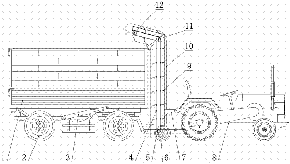
[0025] Such as figure 1 As shown, this specific embodiment includes a carriage 1, a pick-up device and a motor vehicle head 8.
[0026] The bottom of the carriage 1 is provided with traveling wheels I2, and the bottom of the carriage 1 is provided with a hydraulic lifting device 3 that drives the front end of the carriage 1 to lift up and down. between.
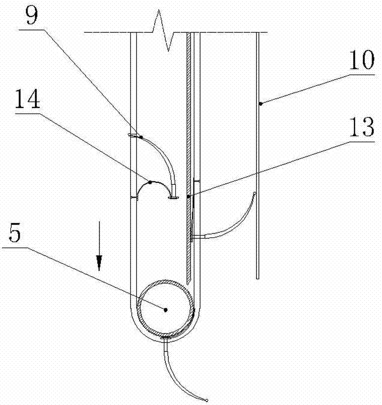
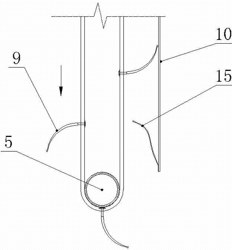
[0027] The afterbody of motor vehicle head 8 is provided with elevating support 7. The picking device includes a lifting conveying device and a walking wheel II6, and the lifting conveying device includes an annular conveying carrier 4, a lower supporting wheel 5, a walking wheel II6, a picking claw 9, a conveying bracket 10, an intermediate supporting wheel 11 and an upper supporting wheel 12.
[0028] The conveying support 10 is fixed on the lifting support 7, and the conveying support 10 includes a 7-shaped cover body. The lower end of the 7-shaped cover body is provided with a material picking port, and the upper end of...
specific Embodiment 2
[0037] Such as Figure 5 As shown, the difference between the second embodiment and the first embodiment is that the lifting conveying device does not have an intermediate support wheel 11, the annular conveying carrier 7 is a 1-shaped ring, and the cover body of the conveying support 10 is also a 1-shaped, and the conveying support 10 Or the carriage 1 is fixed with a blanking plate 19, such as Image 6 As shown, the blanking plate 19 is an arc-shaped plate or an inclined plate, the lower end of the blanking plate 19 is connected to the carriage 1, the higher end of the blanking plate 19 is connected to the upper end of the lifting conveying device, and the blanking plate 19 is provided with a picking claw 9 Through the slot 19-1. Both sides of the blanking plate 19 are also fixed with baffle plates.
specific Embodiment 3
[0038] Such as Figure 7 As shown, the specific embodiment three increases the auxiliary throwing device 20 on the basis of the specific embodiment two, such as Figure 8 As shown, the auxiliary throwing device 20 includes a turntable 22 and a plurality of throwing claws 21 fixed at intervals on the circumference of the turntable 22. All throwing claws 21 are bent in the same direction of rotation, and the bending direction of the throwing claws 21 is the same as that of the picking claws 9. The bending direction is opposite, and the turntable 22 is connected with the upper support wheel 12 by a belt 23, and the belt 23 is crossed into an 8 shape, so that the rotation direction of the turntable 22 and the upper support wheel 12 is opposite, and the picking claw 9 and the throwing claw 21 are on the axis of the turntable 22. To stagger in the direction, the picking claw 9 and the throwing claw 21 rotated to between the turntable 22 and the upper support wheel 12 intersect in th...
PUM
 Abstract
Description
Claims
Application Information
 - R&D Engineer
- R&D Manager
- IP Professional
- Industry Leading Data Capabilities
- Powerful AI technology
- Patent DNA Extraction
Browse by: Latest US Patents, China's latest patents, Technical Efficacy Thesaurus, Application Domain, Technology Topic, Popular Technical Reports.
© 2024 PatSnap. All rights reserved.Legal|Privacy policy|Modern Slavery Act Transparency Statement|Sitemap|About US| Contact US: help@patsnap.com


