Flag-shaped terminal with square tube
A terminal and female terminal technology, applied in the direction of multi-core cable end parts, clamping/spring connection, etc., can solve the problems of large contact surface, unstable connection, and the inability to provide arc-shaped tubular side walls in the slot, etc. Achieve the effect of reducing insertion resistance, avoiding unstable fixation, and good wrapping
- Summary
- Abstract
- Description
- Claims
- Application Information
AI Technical Summary
Problems solved by technology
Method used
Image
Examples
Embodiment 1
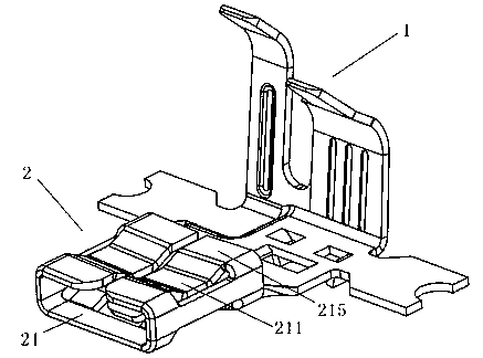
[0029] The structure of the flag-shaped square tube terminal of the present invention is as follows: figure 1 As shown, it includes a cable connection part 1 and a wiring female terminal 2, the wiring direction of the cable connection part 1 is perpendicular to the connection direction of the wiring female terminal 2, and the wiring female terminal 2 is used for inserting wiring A male terminal, the cable connecting part 1 is used for connecting with the cable and covering the cable. The wiring female terminal 2 includes a slot 21; the upper part of the vertical sidewalls on both sides of the slot 21 are respectively provided with two elastic planes 215 extending toward the middle for covering the wiring male terminal. The elastic planes 215 The angle between the plane and the bottom plane of the slot 21 can be adjusted according to different insertion devices. The elastic plane 215 is provided with a concave elastic wall 211 between the two ends along the insertion direction....
Embodiment 2
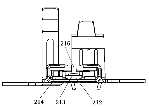
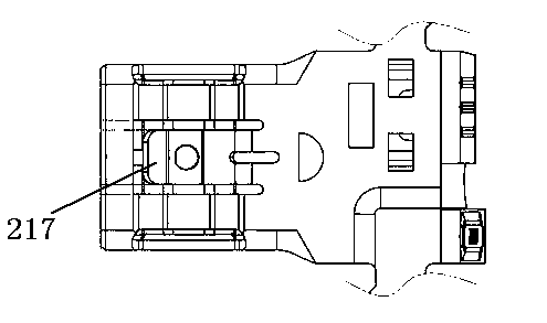
[0031] The flag-shaped square tube terminal in this embodiment is structured as follows image 3 As shown, on the basis of the above-mentioned embodiment, a rectangular hole along the insertion direction is opened in the middle of the bottom surface of the slot 21, and in the rectangular hole, there is a suspension elastic that one end is connected to the bottom of the slot 21 and the other end is suspended. Arm 217 , the suspended end of the suspended elastic arm 217 is close to the socket of the slot 21 . The suspended elastic arm 217 smoothly protrudes 212 inward along the direction of the socket of the slot 21 , such as figure 2 shown. The suspended elastic arm 217 is provided with a convex point 213. Preferably, the convex point 213 is arranged in the middle of the suspended end of the front end of the elastic arm, and preferably a circular convex point is used to cooperate with the groove on the wiring male terminal. Other shapes of bumps can be used to mate with some...
Embodiment 3
[0033] On the basis of the above embodiment, bottom elastic walls 214 are respectively provided on both sides of the suspended elastic arm 217. The bottom elastic wall 214 is formed, and the bottom elastic wall 214 is connected with the bottom of the slot 21 by a slope.
PUM
 Abstract
Description
Claims
Application Information
 - R&D
- Intellectual Property
- Life Sciences
- Materials
- Tech Scout
- Unparalleled Data Quality
- Higher Quality Content
- 60% Fewer Hallucinations
Browse by: Latest US Patents, China's latest patents, Technical Efficacy Thesaurus, Application Domain, Technology Topic, Popular Technical Reports.
© 2025 PatSnap. All rights reserved.Legal|Privacy policy|Modern Slavery Act Transparency Statement|Sitemap|About US| Contact US: help@patsnap.com


