Magnetofluid deformable mirror device
A deformable mirror and magnetic fluid technology, applied in optical components, optics, instruments, etc., can solve the problems of non-linear response of mirror surface, increase the deformation amplitude of mirror surface response, etc., and achieve the effect of easy expansion, low cost and good application prospect.
- Summary
- Abstract
- Description
- Claims
- Application Information
AI Technical Summary
Problems solved by technology
Method used
Image


Examples
Embodiment 1
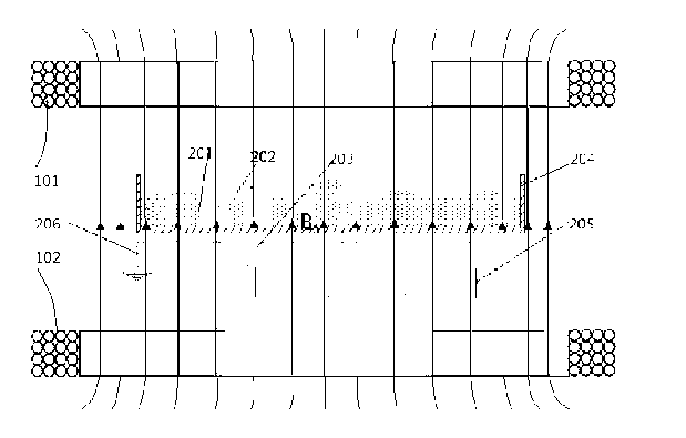
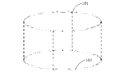
[0028] In this embodiment, see figure 1 and figure 2 , A magnetic flow device device, including the basic mirror system and mirror deformation driving system, specifically: put the iron magnetic fluid 201 in the container 204, and then pour the metal -like liquid reflective membrane material on the iron magnetic fluid 201.Forms a metal -like liquid reflective membrane 202 floating on the iron magnetic fluid 201 liquid surface, and the basic mirror system that constitutes a magnetic flow deformation mirror; set the micro -electromagnetic coil group 203 below the container 204, the micro -electromagnetic coil group 203 is connected to the wire 205 to connect the connectionEntering the driver circuit, the micro -electromagnetic coil group 203 is also connected to the ground with another wire 206 to form a mirror deformation driving system that constitutes a magnetic flow deformation mirror, so that the iron magnetic fluid 201 is under the basic electromagnetic field; it is also set o...
Embodiment 2
[0038] The example of this embodiment is:
[0039] In this embodiment, see Figure 4, Compare the mirror deformation response of the above -mentioned Example One Magnetic Flint Mirror Device with the mirror deformation amplitude of the mirror deformation response of the traditional magnetic flow deformation mirror with the current curve of the input miniature electromagnetic coil group.Whether the mirror deformation response of the fluid transformer device has linear characteristics.
[0040] Example One Magic Flow Transformers Mirror Device Mirror Response Linear Professional Verification Method Specific Implementation Step is:
[0041] 1) Detect and record a miniature electromagnetic coil of the traditional magnetic flow deformation mirror separately into the current of the deformation amplitude characteristic curve of the corresponding position of the mirror surface;
[0042] 2) Detect and record the Micro -electromagnetic coil corresponding to the micro -electromagnetic coil co...
Embodiment 3
[0046] The example of this embodiment is:
[0047] In this embodiment, see Figure 5 , Adopt an Example One Magnetic Flutter Transformer Device to verify the specific implementation steps of the mirror response of the implementation of the mirror response of the magnetic flow mirror device.
[0048] 1) Select the two adjacent miniature electromagnetic coils in the mirror deformation driving system of the Magnetic Flint Mirror Device in any Magnetic Flow Transformer Mirror device at will, which are marked with 'a' and 'b', respectively.Location as an observation point C;
[0049] 2) To the mirror deformation drive system of the embodiment one magnetic flow mirror device, the micro -electromagnetic coil marked with ‘A’ separated by the current signal of the current signal 1, detect and record the deformation amplitude characteristic curve of the observation point C;
[0050] 3) To the mirror deformation drive system of the embodiments one magnetic fluid transformer device, the micro ...
PUM
 Abstract
Description
Claims
Application Information
 - R&D
- Intellectual Property
- Life Sciences
- Materials
- Tech Scout
- Unparalleled Data Quality
- Higher Quality Content
- 60% Fewer Hallucinations
Browse by: Latest US Patents, China's latest patents, Technical Efficacy Thesaurus, Application Domain, Technology Topic, Popular Technical Reports.
© 2025 PatSnap. All rights reserved.Legal|Privacy policy|Modern Slavery Act Transparency Statement|Sitemap|About US| Contact US: help@patsnap.com