
Rear smoke channel of biomass boiler and biomass boiler

A biomass boiler and tail flue technology, which is applied in the direction of combustion product treatment, combustion method, exhaust gas device, etc., can solve the problems of reducing boiler output, easy ash accumulation, safety accidents, etc., and achieve the effect of solving ash accumulation

Active Publication Date: 2013-08-07
CHINA CAMC ENG
View PDF3 Cites 2 Cited by
  • Summary
  • Abstract
  • Description
  • Claims
  • Application Information

AI Technical Summary

Problems solved by technology

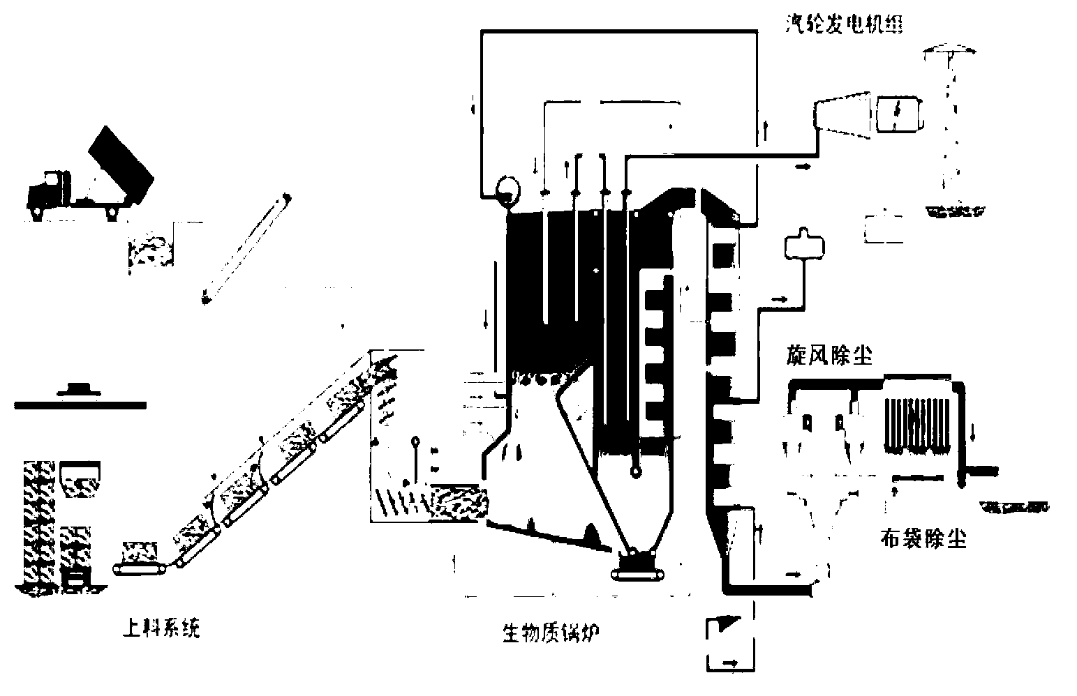
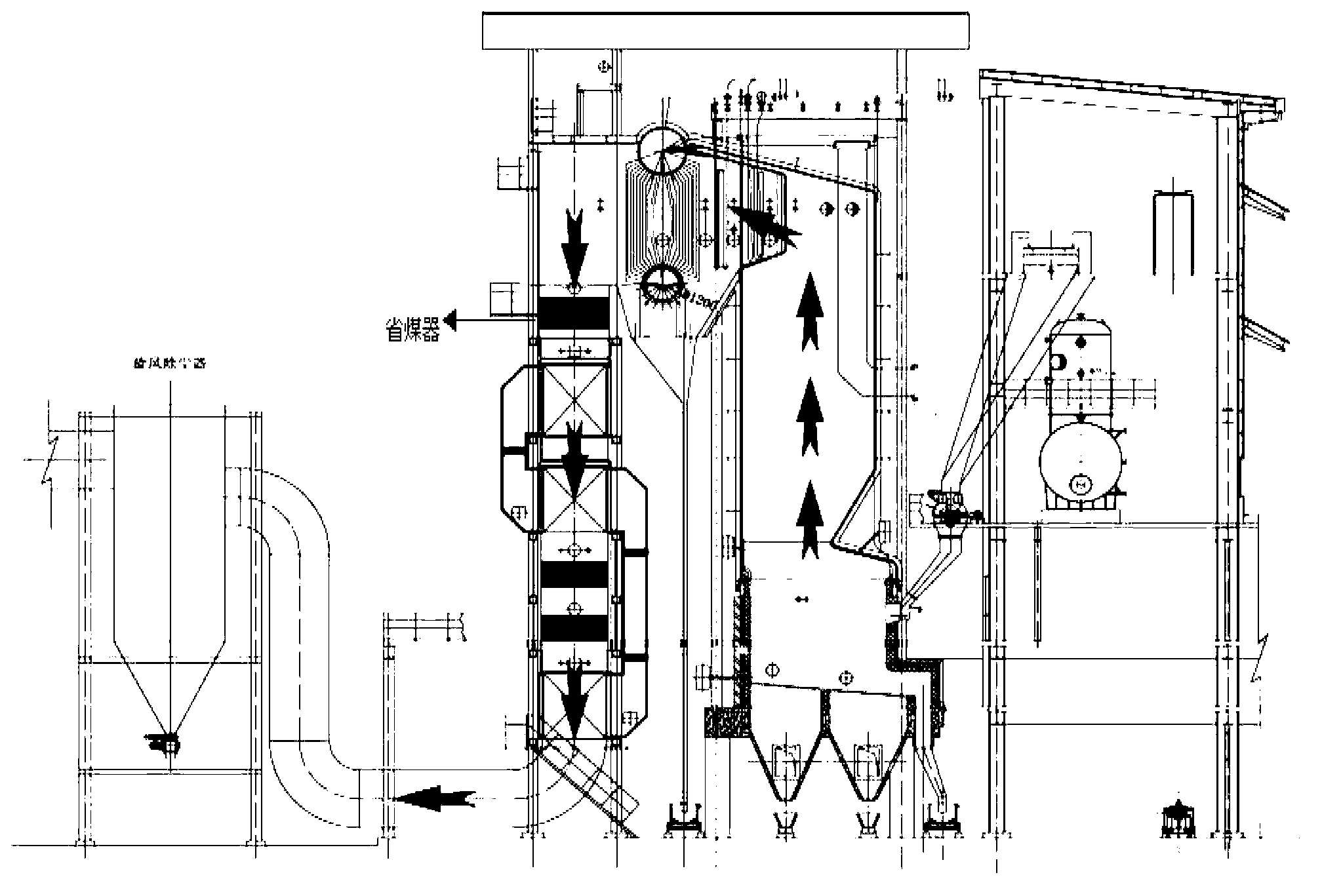
The fuel reaches the biomass boiler through the feeding system, and generates flue gas after combustion. The flue gas passes through the tail flue, and finally passes through the external dust removal device for dust removal and then discharges. The flue gas flow direction of the boiler tail flue is shown by the arrow in the figure. From top to bottom, under the action of its own gravity, the dust is easy to accumulate dust for the horizontal tube bundle economizer shown in the figure, and the boiler dust accumulation is likely to cause the following problems: 1. Cause safety accidents; 2. Reduce Thermal efficiency, waste of fuel; 3. Reduce boiler output; 4. Reduce boiler life; 5. Reduce economic benefits

Method used


Image

  • Rear smoke channel of biomass boiler and biomass boiler
  • Rear smoke channel of biomass boiler and biomass boiler
  • Rear smoke channel of biomass boiler and biomass boiler

Examples


Embodiment Construction

[0029] In order to make the structure, characteristics and advantages of the present invention clearer, prior to the detailed description below in conjunction with specific embodiments, the prior art mentioned in the background art section will be described in conjunction with the accompanying drawings.

[0030] figure 1 and figure 2 It is respectively a schematic diagram of a common boiler and its dust removal device in the prior art.

[0031] refer to figure 1 Shown is a schematic diagram of a typical layer combustion plus suspension combustion biomass boiler and dust removal system in the prior art. This typical layer combustion plus suspension combustion biomass boiler and dust removal system is generally composed of the feeding system indicated in the figure , a biomass boiler connected to the feeding system, and an external dust removal device, specifically, the external dust removal device includes: cyclone dust collector and bag dust removal equipment. The fuel rea...


PUM


Abstract

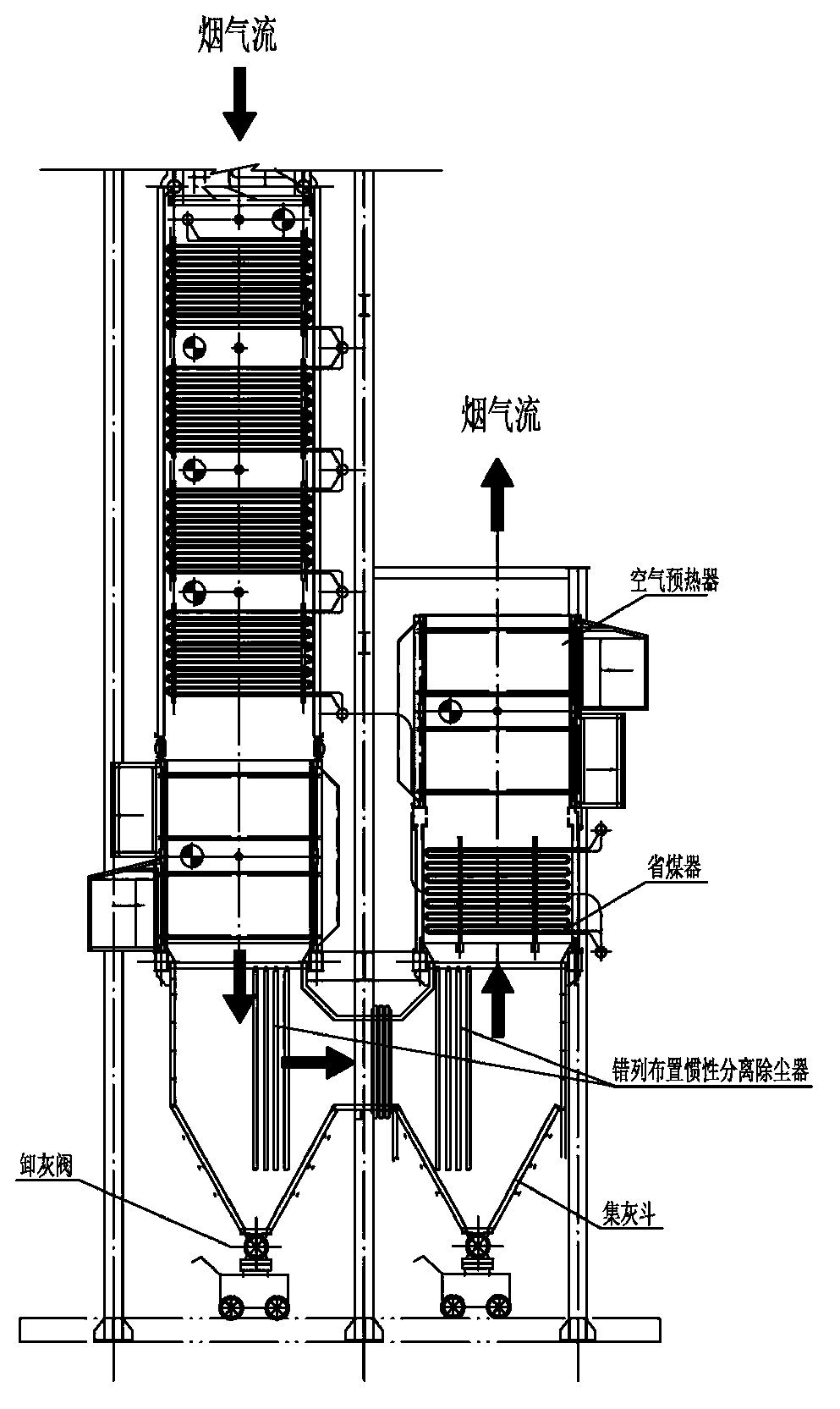
The invention provides a rear smoke channel of a biomass boiler and the biomass boiler. The rear smoke channel of the biomass boiler is arranged in a U shape, and smoke descends from the top of the rear smoke channel to the bottom and then rises from the bottom to the top. The rear smoke channel comprises dust removing devices, an ash bucket, one or more economizers and a first air preheater, wherein dust removing devices are located at positions of two corners of a U-shaped flow line of the smoke, the ash bucket is located under dust removing devices, dust removing baffle plates are arranged inside dust removing devices, when smoke dust in the smoke collides with dust removing baffle plates, the smoke dust changes directions and falls into the ash bucket under the action of gravity, one or more economizers are located at a position where the smoke flows from bottom to top, and the first air preheater is located above one or more economizers which are arranged at the position where the smoke flows from bottom to top. By the aid of the rear smoke channel of the biomass boiler and the biomass boiler, the automatic dust removing capability of the boiler can be improved, the land occupied by the dust removing device of the boiler and the investment cost can be reduced, and various problems caused by ash deposition of the boiler can be solved.

Description

technical field [0001] The invention relates to the field of mechanical equipment, in particular to a tail flue of a biomass boiler and a biomass boiler. Background technique [0002] Biomass such as crop stalks, bagasse, and rice husks are fed into boilers for combustion as fuel, and the steam generated is used for power generation or heating. This is a biomass energy utilization technology advocated by the state. According to the characteristics of biomass fuel, it is a common and mature combustion process to use layer combustion plus suspension combustion, or suspension combustion, or circulating fluidized bed combustion. The original emission concentration is relatively high (the dust removal efficiency of the dust collector after the furnace must reach more than 99.8% to meet the current environmental protection emission requirements), and the flue gas often contains particles with sparks, which may damage the bag filter behind the furnace harm. [0003] refer to fig...

Claims


Application Information

Patent Timeline
Patent Type & Authority Applications(China)
IPC IPC(8): F23J11/00F23J15/00F23J15/06
Inventor 洪浩
Owner CHINA CAMC ENG
Learn More