
Ceramic medium-and-low pressure slip-casting device

A grouting molding and low-pressure technology, which is applied in the field of sanitary ware ceramic processing and production, can solve the problems of inconvenient mobilization of moulds, high recruitment and labor costs, and high production costs, so as to protect workers' health, facilitate maintenance and disassembly, and reduce labor costs. Effect

Inactive Publication Date: 2013-08-07
广州市奈迪自动化设备有限公司
View PDF4 Cites 7 Cited by
  • Summary
  • Abstract
  • Description
  • Claims
  • Application Information

AI Technical Summary

Problems solved by technology

[0002] At present, the known grouting methods mainly rely on the traditional overpass line grouting molding process and high-pressure grouting molding process, but these two types of processes are mostly completed manually, with high production costs, low output, and low efficiency. At the same time, due to the above The process needs the experience of the staff, so the above production methods also face many contradictions such as difficulty in recruiting workers, long training time, insufficient technical ability of employees, and insufficient market supply.
At the same time, due to the high-temperature and high-humidity environment required by the ordinary overpass molding process, coupled with the poor regularity of the green body, the dust generated by trimming has a greater impact on the health of employees, resulting in difficulties in line planning for production planning, inconvenient transfer of molds, and labor recruitment. High labor cost

Method used


Image

  • Ceramic medium-and-low pressure slip-casting device
  • Ceramic medium-and-low pressure slip-casting device

Examples


Embodiment Construction

[0020] Referring to the accompanying drawings and specific embodiments below, the present invention will be further described:

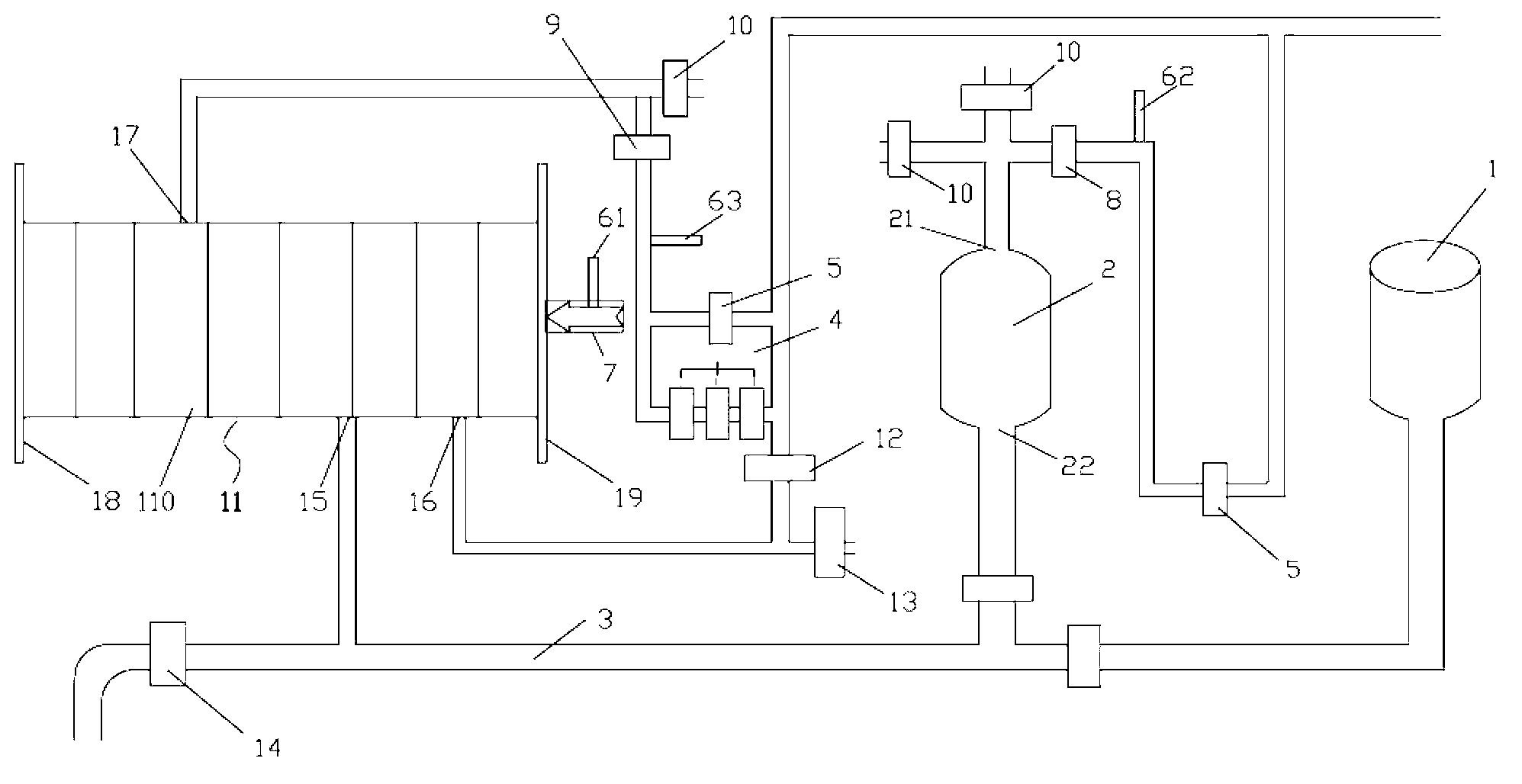
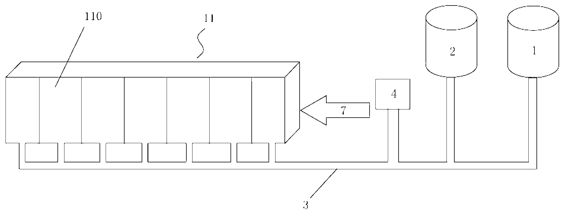
[0021] see figure 1 , the medium and low-pressure grouting molding device for ceramics according to the present invention includes an atmospheric pressure slurry cylinder 1, a pressurized slurry cylinder 2 and a mold group 11 connected in sequence by a slurry delivery pipe 3, and also includes a control unit 4 for compacting The propulsion unit 7 of the mold set 11, the first pressure sensor 61 for detecting the internal pressure of the mold set 11 and the execution unit 5 for issuing instructions to the control unit 4, the execution unit 5 and the first pressure sensor 61 are connected with the control unit 4, and the propulsion unit 7 is connected with the execution unit 5.

[0022] In this embodiment, the pressurized pulp cylinder 2 is provided with an air pressure port 21 and a slurry pressurized port 22, and an exhaust valve group and a pressur...


PUM


Abstract

The invention relates to a ceramic medium-and-low pressure slip-casting device. The ceramic medium-and-low pressure slip-casting device comprises a constant-pressure slurry tank, a pressurized slurry tank, a mould group, a control unit, a pushing unit for pressing the mould group tightly, a first pressure sensor for detecting pressure inside the mould group and an execution unit for issuing an instruction to the control unit, wherein the constant-pressure slurry tank, the pressurized slurry tank and the mould group are connected in sequence through slurry delivering pipes. The execution unit and the first pressure sensor are connected with the control unit, and the pushing unit is connected with the execution unit. The slip-casting device adopts the control unit to control the slip-casting process, enables the slip-casting process to be finished automatically, and greatly reduces the labor cost while improving the production efficiency. Compared with the prior art, the device is small in occupied area, short in moulding time, free of dust in a work environment and low in labor intensity, ensures worker health, and has the advantages of being durable, long in service life and convenient to maintain and dismantle.

Description

technical field [0001] The invention relates to the field of ceramic processing and production of sanitary ware, in particular to a medium-low pressure automatic grouting molding device for ceramics. Background technique [0002] At present, the known grouting methods mainly rely on the traditional overpass line grouting molding process and high-pressure grouting molding process, but these two types of processes are mostly completed manually, with high production costs, low output, and low efficiency. At the same time, due to the above The process requires the experience of the staff, so the above production methods also face many contradictions such as difficulty in recruiting workers, long training time, insufficient technical ability of employees, and insufficient market supply. At the same time, due to the high-temperature and high-humidity environment required by the ordinary overpass molding process, coupled with the poor regularity of the green body, the dust generate...

Claims


Application Information

Patent Timeline
IPC IPC(8): B28B1/26
Inventor 袁东福
Owner 广州市奈迪自动化设备有限公司
Learn More