Fuel injection system

A fuel injection system, injection system technology, applied to fuel injection pumps, fuel injection devices, charging systems, etc., to achieve small current requirements, improve overall power efficiency, and reduce power loss

Inactive Publication Date: 2013-07-31
ROBERT BOSCH GMBH
View PDF5 Cites 1 Cited by
  • Summary
  • Abstract
  • Description
  • Claims
  • Application Information

AI Technical Summary

Problems solved by technology

[0007] Disadvantageously, with known mechanically driven fuel pumps, adaptat...

Method used


Image

  • Fuel injection system
  • Fuel injection system
  • Fuel injection system

Examples


Embodiment Construction

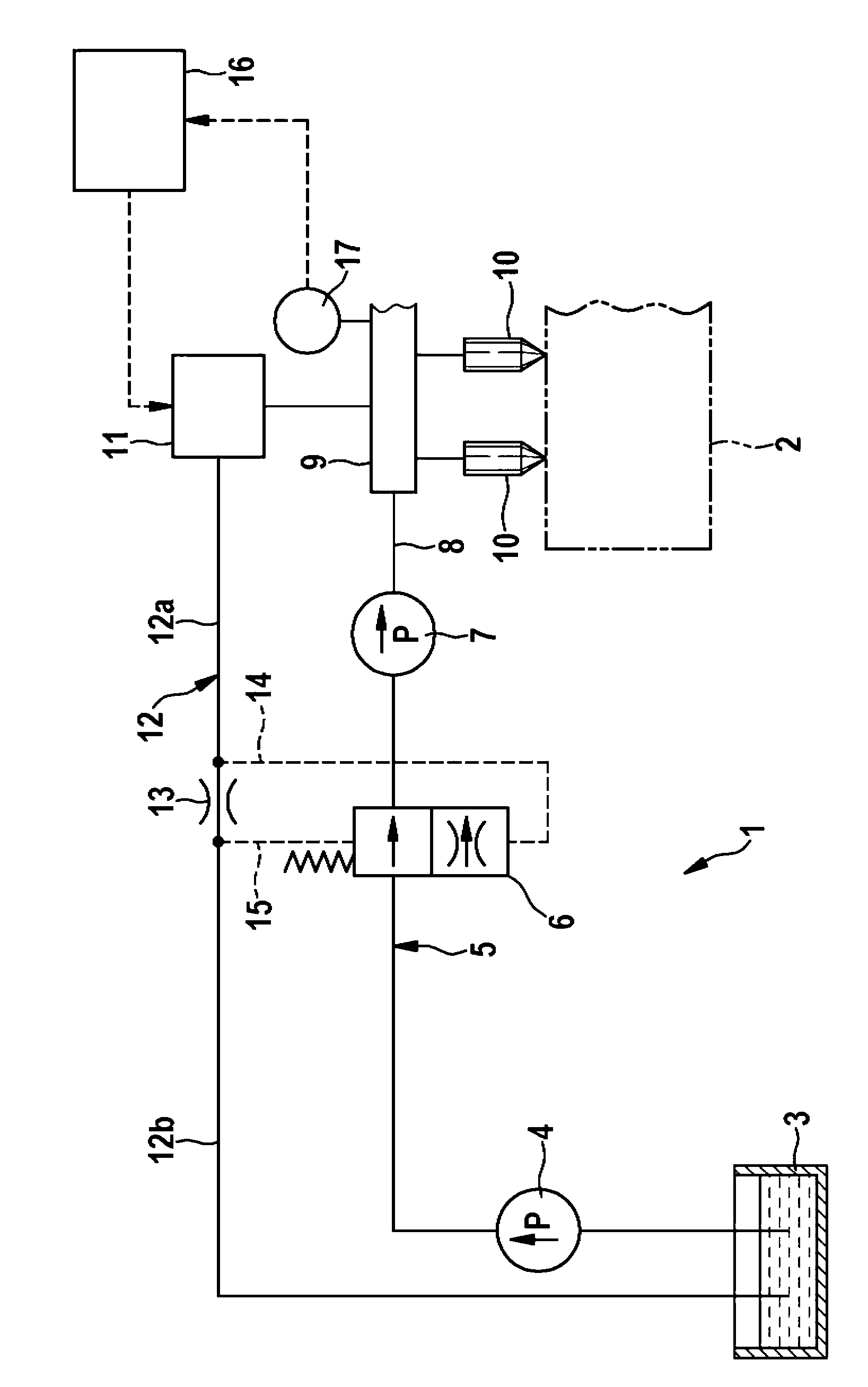
[0024] FIG. 1 shows a prior art fuel injection system 1 for supplying an internal combustion engine 2 , however it is only schematically represented in FIG. 1 by dotted lines. The fuel injection system 1 comprises a fuel container 3 from which an electrically driven fuel delivery pump 4 delivers fuel into a low-pressure line 5 to a measuring unit 6 . Downstream of the measuring unit 6 , the low-pressure line 5 feeds a high-pressure pump 7 mechanically driven by the internal combustion engine 2 . The high-pressure pump 7 compresses the fuel to a very high pressure and delivers them via the high-pressure line 8 into a high-pressure accumulator 9, also called a "rail". A plurality of injectors 10 are connected to said rails, injecting fuel into the combustion chambers of the internal combustion engine 2, not shown.

[0025] The exhaust control valve 11 is connected to the high-pressure accumulator 9 , and the exhaust pipeline 12 is controlled by the exhaust control valve 11 to r...


PUM


Abstract

The invention relates to a fuel injection system of an internal combustion engine, in particular a common rail injection system, comprising a mechanical fuel delivery pump, which supplies fuel to a high pressure pump via a low pressure line. The high pressure pump feeds highly pressurized fuel to a high pressure accumulator via a high pressure line, wherein the delivery volume of the fuel delivery pump can be regulated via a pressure controller.

Description

technical field [0001] The invention relates to a fuel injection system for an internal combustion engine, in particular a common rail injection system, according to the preamble of claim 1 . Background technique [0002] In the prior art, high-pressure injection systems, such as common rail systems, are known, which have a high-pressure pump to supply high-pressure fuel to the fuel storage, wherein a mechanical or electrical transfer pump transfers the fuel from the fuel tank to the High-pressure pump. [0003] For the delivery of fuel to the high-pressure pump, different delivery pump concepts are used here, such as internal or external delivery gear pumps and vane pumps. The different feed pumps used have a delivery volume which is reliably predetermined by the pump geometry, which is also limited to a maximum volume, for example by means of a throttle valve installed on the suction side. [0004] In order to meet the starting conditions of the motor vehicle, relatively...

Claims


Application Information

Patent Timeline
IPC IPC(8): F02M59/34F02M59/36F02M59/44F02M37/00F02M63/02
CPCF02M63/0028F02M37/0029F02M59/447F02M63/0056F02M59/34F02M63/023
Inventor C·朗根巴赫J·莫洛克
Owner ROBERT BOSCH GMBH
Why Eureka
Try Eureka