Eureka AIR delivers breakthrough ideas for toughest innovation challenges, trusted by R&D personnel around the world.

Distance measuring device

A technology of distance measurement and distance, which is applied in the field of distance measurement (measurement) devices, which can solve the problems of image processing calculation cost increasing with distance accuracy and subject not being available, and achieving low component cost and low computing cost

Inactive Publication Date: 2013-07-31
HITACHI LTD
View PDF3 Cites 18 Cited by
  • Summary
  • Abstract
  • Description
  • Claims
  • Application Information

AI Technical Summary

Problems solved by technology

In addition, in the stereoscopic distance measurement method that uses multiple cameras to shoot the same subject, and measures the distance information to the subject based on the difference in the visual performance of the subject in the images of the two cameras, although there is no A special light source is required, but the correct distance cannot be obtained for objects without texture, etc. In addition, there are problems such as the increase in the calculation cost of image processing with the distance accuracy

Method used


Image

  • Distance measuring device
  • Distance measuring device
  • Distance measuring device

Examples


Embodiment 1

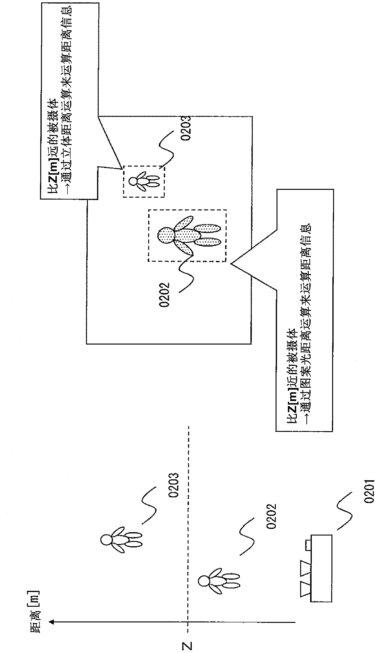
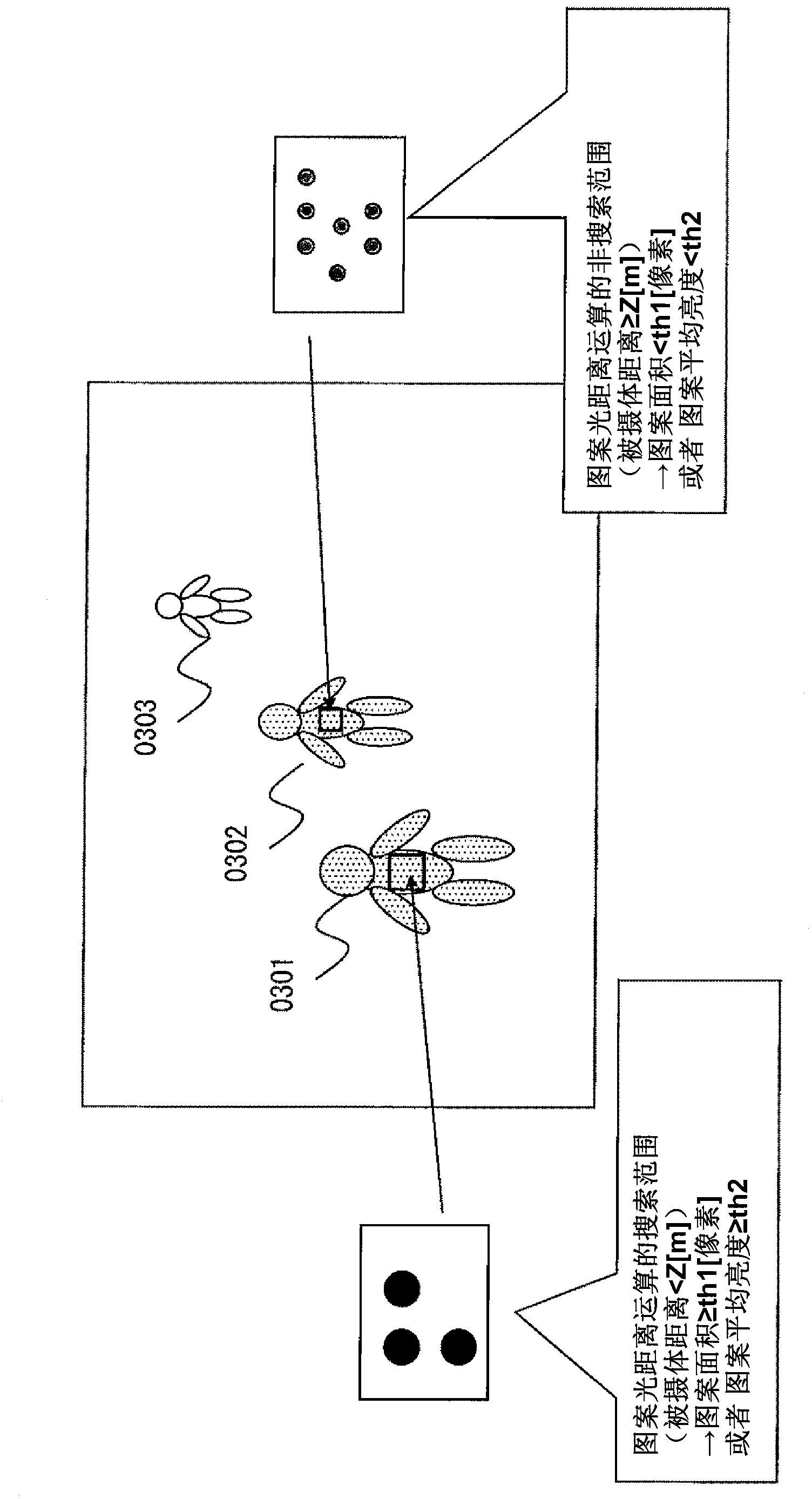
[0114] figure 1 is a first schematic view showing the distance measuring device according to the first embodiment of the present invention. figure 1 Among them, 0101 is the first imaging unit, 0102 is the second imaging unit, 0103 is the infrared pattern projection unit, 0104 is the pattern light distance calculation unit, 0105 is the stereo distance calculation unit, 0106 is the distance calculation control unit, and 0107 is the distance information integration Section, 0108 is an image output section.

[0115] figure 1 In the shown distance measuring device, the photographing unit 0101 is appropriately composed of a lens group including a zoom lens and a focus lens, a diaphragm, a shutter, a photosensitive element such as CCD or CMOS, a CDS, an AGC, an AD converter, and the like. The optical image is photoelectrically converted, and the camera signal processing such as noise removal, edge emphasis and gamma processing is performed, and the image signal is output. The phot...

Embodiment 2

[0135] Figure 12 is a schematic diagram showing a distance measuring device according to a second embodiment of the present invention. Figure 12 Among them, 1201 is the first photographing unit, 1202 is the second photographing unit, 1203 is the infrared pattern projection unit, 1204 is the pattern light distance calculation unit, 1205 is the three-dimensional distance calculation unit, 1206 is the distance calculation control unit, 1207 is the distance information integration 1208 is an image output unit, 1210 is a timing control unit, and 1211 is an object tracking unit. figure 1 In the first schematic diagram showing the distance measuring device according to the first embodiment of the present invention, a timing control unit 1210 and an object tracking unit 1211 are added.

[0136] Figure 12 In the distance measurement device shown, the timing control unit 1210 controls the timing information output by the distance measurement control unit 1206, during the projection...

Embodiment 3

[0141] Figure 15 is a schematic diagram showing a distance measuring device according to a third embodiment of the present invention. Figure 15 Among them, 1501 is the first imaging unit, 1502 is the second imaging unit, 1502_1 is the camera signal processing unit for stereo calculation, 1502_2 is the camera signal processing unit for image output, 1503 is the infrared pattern projection unit, 1504 is the pattern light distance calculation unit , 1505 is a three-dimensional distance calculation unit, 1506 is a distance calculation control unit, 1507 is a distance information integration unit, 1508 is an image output unit, relative to figure 1 The shown first schematic diagram of the distance measuring device according to the first embodiment of the present invention, the second photographing part 1502 has a plurality of camera signal processing parts.

[0142] Figure 15 In the shown distance measuring device, the imaging unit 1502 is composed of a lens group including a z...


PUM


Abstract

The present invention relates to a distance measuring device provided with a distance measuring function of a patterned-light projection scheme and a distance measuring function of a stereo scheme using a plurality of camera images. The distance measuring device comprises first imaging means having spectral response characteristics in a wavelength band of visible light and in a predetermined wavelength band of invisible light; second imaging means having spectral response characteristics in the wavelength band of the visible light, the second imaging means having no spectral response characteristics in the predetermined wavelength band of the invisible light; invisible-light projection means; invisible-light-aided distance computation means adapted to conduct image processing of an image formed by and output from the first imaging means, then compute a first distance to a target subject and output the first distance information; stereo distance computation means adapted to conduct stereo image processing of both the image formed by and output from the first imaging means and an image formed by and output from the second imaging means, then compute a second distance to the subject, and output the second distance information; and distance computation control means adapted to control computation conditions used for the invisible-light-aided distance computation means and the stereo distance computation means to conduct the respective computations.

Description

technical field [0001] The present invention relates to a distance measurement (measurement) device having a distance measurement function of an infrared pattern light projection method and a distance measurement function of a stereo method using a plurality of camera images. Background technique [0002] As the background technology of this technical field, for example, in Patent Document 1, the technical problem is "to provide a distance image generation device capable of generating a high-precision distance image without increasing the size of the device and increasing the cost", and as The technical means to solve this problem discloses such a technology, that is, "two imaging parts PA and PB are provided in the video camera 10, images formed by light in the visible light band are acquired from the imaging part PA and the imaging part PB, and stereo matching is used to method to generate a distance image A. On the other hand, the imaging unit PB can acquire an image form...

Claims


Application Information

Patent Timeline
Patent Type & Authority Applications(China)
IPC IPC(8): G01C3/00
CPCG01C11/025G01C3/14
Inventor 广冈慎一郎
Owner HITACHI LTD
Why Eureka
Eureka Blog
Learn More