Hydraulic direction-changing valve, hydraulic direction-changing valve set and engineering machinery

A technology of hydraulic reversing valve and construction machinery, applied in mechanical equipment, servo motor components, fluid pressure actuating devices, etc., can solve the problem of reducing the effective flow area of ​​oil return, the impact of the boom cylinder, and the increase of the oil inlet pressure. And other issues

Active Publication Date: 2013-07-31
CHANGDE ZHONGLIAN ZHONGKE HYDRAULIC +1
View PDF5 Cites 4 Cited by
  • Summary
  • Abstract
  • Description
  • Claims
  • Application Information

AI Technical Summary

Problems solved by technology

For example, in the reversing valve with the oil return function of the middle position, it often occurs that the hydraulic valve is switched from the middle position to other working positions. Since the oil inlet needs to supply pressure oil to the working oil port, the effective oil return is required. The flow area becomes smaller, and at a certain moment it will suddenly become very small, which will cause the pressure of the oil inlet to increase suddenly, which will cause an impact on the corresponding working oil port at this moment, and then cause the impact of the actuator, for example It will cause a large impact on the boom cylinder, which will also have an adverse effect on the working performance of the construction machinery
[0003] In addition, in the hydraulic reversing valve group, when multiple actuators act at the same time, because the corresponding multiple reversing valves are connected to each other, the actuator that acts later will cause the actuator that acts earlier to suddenly accelerate.
For example, when the reversing valve that controls the action of the luffing cylinder is in the transition position, part of the oil entering the reversing valve will return oil through the reversing valve that controls the winch motor, and the other part will supply oil to the luffing cylinder. At this time, if the winch motor is operated at the same time, the oil return of the reversing valve controlling the luffing cylinder will be partially cut off when the reversing valve controlling the winch motor is operated, so that the reversing valve controlling the luffing cylinder will be cut off at this moment. The flow rate from the inner oil inlet to the working oil port suddenly increases, and this sudden acceleration process will cause a sudden change in the luffing speed of the boom and cause the boom to shake, which not only affects the operation performance of the construction machinery, but also easily causes unnecessary accidents

Method used


Image

  • Hydraulic direction-changing valve, hydraulic direction-changing valve set and engineering machinery
  • Hydraulic direction-changing valve, hydraulic direction-changing valve set and engineering machinery
  • Hydraulic direction-changing valve, hydraulic direction-changing valve set and engineering machinery

Examples


Embodiment Construction

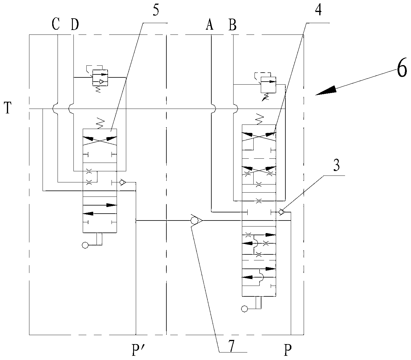
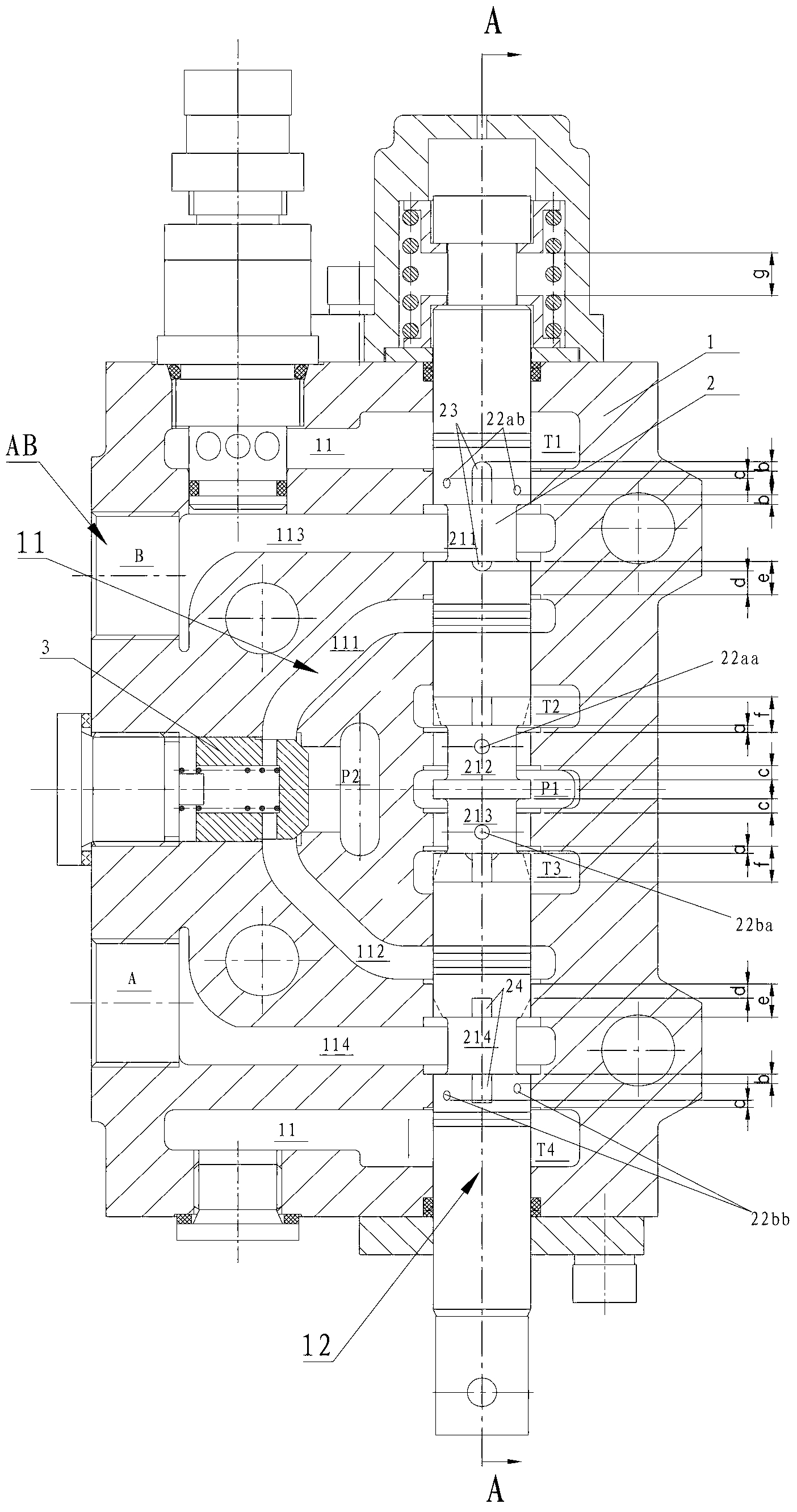
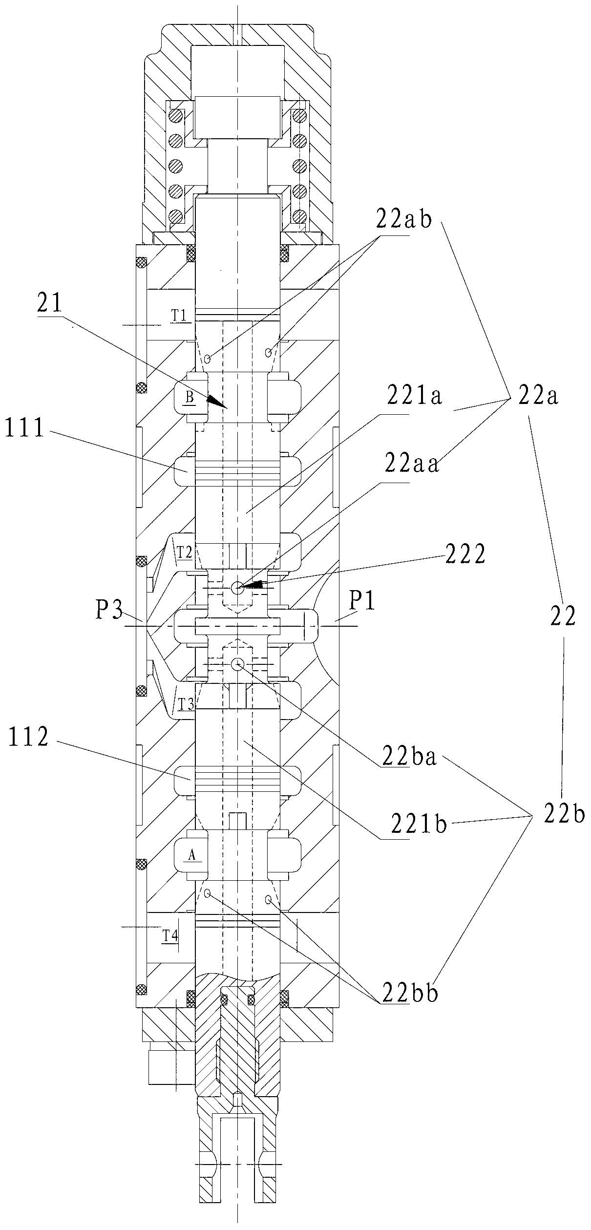
[0038] Specific embodiments of the present invention will be described in detail below in conjunction with the accompanying drawings. It should be understood that the specific embodiments described here are only used to illustrate and explain the present invention, and are not intended to limit the present invention.

[0039] In the present invention, in the case of no contrary description, the used orientation words such as "up, down" are attached figure 2 and image 3 The direction of the drawing is defined as the benchmark, while "inner and outer" is based on the axial center of the valve stem. The side of the corresponding component close to the axial center is the inner side, and the side farther from the axial center is the On the outside, in addition, "axial and radial" are defined on the basis of the length direction of the valve stem, that is, the length direction of the valve stem is the axial direction, and the radial direction is perpendicular to the length direc...


PUM


Abstract

The invention discloses a hydraulic direction-changing valve, a hydraulic direction-changing valve set and engineering machinery. The hydraulic direction-changing valve comprises a valve body and a valve rod; a plurality of inner flow channels and a valve port used for communicating the plurality of flow channels, as well as an oil inlet, an oil return port and working oil ports all communicated with the corresponding inner flow channels, are formed in the valve body; diversion trenches are formed in the outer side of the valve body; the valve rod can move axially in the valve port to open or close corresponding inner channel, so that the hydraulic oil of the hydraulic direction-changing valve can perform oil returning; a valve rod flow channel is formed inside the valve rod; when shifting from the middle station to other stations, the valve rod flow channel can communicate the oil inlet and the corresponding working oil port which is supplied by the oil inlet; or communicate the oil inlet and the oil return port; the hydraulic direction-changing valve set adopts the hydraulic direction-changing valve provided by the invention; and the engineering machinery adopts the hydraulic direction-changing valve set provided by the invention.

Description

technical field [0001] The invention relates to the field of hydraulic reversing valves, in particular to a hydraulic reversing valve, a hydraulic reversing valve group using the hydraulic reversing valve, and an engineering machine using the hydraulic reversing valve group. Background technique [0002] In the field of construction machinery, hydraulic reversing valve groups are usually used. For the convenience of use, the hydraulic reversing valve group as the main reversing valve is usually designed as an integrated composite valve, that is, a multi-way reversing valve. Taking a crane as an example, its main reversing valve usually includes a hydraulic reversing valve that controls boom luffing and winch retraction. The two reversing valves are connected to each other to complete the jib luffing operation of the crane and the hoisting and retracting operation respectively. Specifically, one reversing valve controls the jib cylinder and the other controls the hoisting mot...

Claims


Application Information

Patent Timeline
IPC IPC(8): F15B13/02
Inventor 刘先爱潘文华
Owner CHANGDE ZHONGLIAN ZHONGKE HYDRAULIC
Why Eureka
Try Eureka