
Loading device of mixing machine

Inactive Publication Date: 2013-07-31
中科鑫洋(江苏)生物技术有限公司
View PDF0 Cites 3 Cited by
  • Summary
  • Abstract
  • Description
  • Claims
  • Application Information

AI Technical Summary

Problems solved by technology

At present, most of the materials are poured into the material mixer manually through the barrel. Due to the high height of the material mixer, the operator needs to climb up through the ladder. The operation is cumbersome, the work efficiency is low, and it is not safe.

Method used


Image

  • Loading device of mixing machine

Examples


Embodiment Construction

[0008] The specific content of the present invention will be described in detail below in conjunction with the accompanying drawings and specific embodiments.

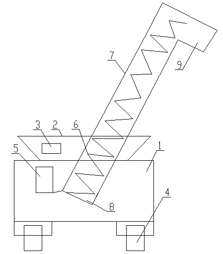
[0009] Such as figure 1 As shown, the feeding device of the mixer includes: a material box 1, a feed port 2 arranged at the upper end of the material box 1, a vibrating motor 3 is arranged outside the feed port 2, and a roller 4 is provided at the lower end of the material box 1 , a driving motor 5 and a conveying screw 6 connected to the driving motor 5 are arranged in the feed box 1, the conveying screw 6 is arranged in the conveying pipe 7, and a feed port 8 is arranged at the lower end of the conveying pipe 7, and the feeding The mouth 8 is arranged in the material box 1 , and the upper end of the conveying pipe 7 is provided with a discharge outlet 9 .

[0010] In the feeding device of the above-mentioned mixer, the material enters the material box 1 through the feed port 2 at the upper end of the material box 1,...


PUM


Abstract

The invention discloses a loading device of a mixing machine. The loading device of the mixing machine is high in working efficiency and comprises a feed box and a feed opening formed in the upper end of the feed box, wherein a vibrating motor is arranged on the outer side of the feed opening; rollers are arranged at the lower end of the feed box; a driving motor and a convey screw rod connected with the driving motor are arranged in the feed box; the convey screw rod is arranged in a conveying pipe; a feed inlet is formed in the lower end of the conveying pipe and in the feed box; and a discharge opening is formed in the upper end of the conveying pipe. The loading device of the mixing machine has the advantages of mechanically automatic loading, high working efficiency, convenience in operation and loading safety.

Description

technical field [0001] The invention relates to a mixer feeding device. Background technique [0002] Material mixers are used in pharmaceutical, chemical, food, electronics, machinery, metallurgy and other industries. Now most of the materials are poured into the material mixer manually through the material barrel. Due to the high height of the material mixer, the operator needs to climb up through the ladder. The operation is troublesome, the work efficiency is low, and it is not safe. Contents of the invention [0003] The technical problem to be solved by the present invention is to provide a mixer feeding device with high working efficiency. [0004] In order to solve the above-mentioned technical problems, the technical solution adopted in the present invention is: the feeding device of the mixer, comprising: a material box, a feed port arranged on the upper end of the material box, a vibrating motor is arranged outside the feed port, Rollers are arranged at the lo...

Claims


Application Information

Patent Timeline
Patent Type & Authority Applications(China)
IPC IPC(8): B65G65/46
Inventor 谢洪畴王金霞王海琴
Owner 中科鑫洋(江苏)生物技术有限公司
Learn More