
Heat pipe bending machine

A bending machine and bending mechanism technology, applied in metal processing equipment, feeding devices, positioning devices, etc., can solve the problems of not being able to meet the different needs of heat pipe bending, not being able to realize digital control, and the bending accuracy is not very high , to achieve the effect of protecting the bending quality, ingenious design and beautiful appearance

Inactive Publication Date: 2013-07-31
游本俊
View PDF6 Cites 7 Cited by
  • Summary
  • Abstract
  • Description
  • Claims
  • Application Information

AI Technical Summary

Problems solved by technology

In order to improve the heat transfer performance, heat pipes are generally bent into a certain arc shape. The current bending method of heat pipes is mainly manual operation. It is difficult to control the force during manual bending, and the rate of defective processing is relatively high. High, which increases the consumption of raw materials and consumes more human resources, which affects production efficiency
There are a few that use bending machines for bending, but at present, the bending machines are basically controlled by mechanization, and digital control cannot be realized, so the bending accuracy is not very high, and the existing bending machines can only Bending with a single shape, if you want to change the bending shape of the heat pipe, the existing bending machine may not be able to achieve or need to be modified to perform bending, which cannot meet the different needs of heat pipe bending

Method used


Image

  • Heat pipe bending machine
  • Heat pipe bending machine
  • Heat pipe bending machine

Examples


Embodiment Construction

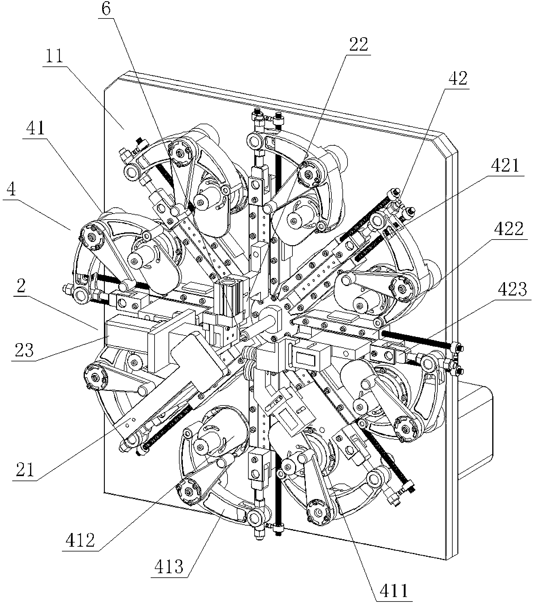
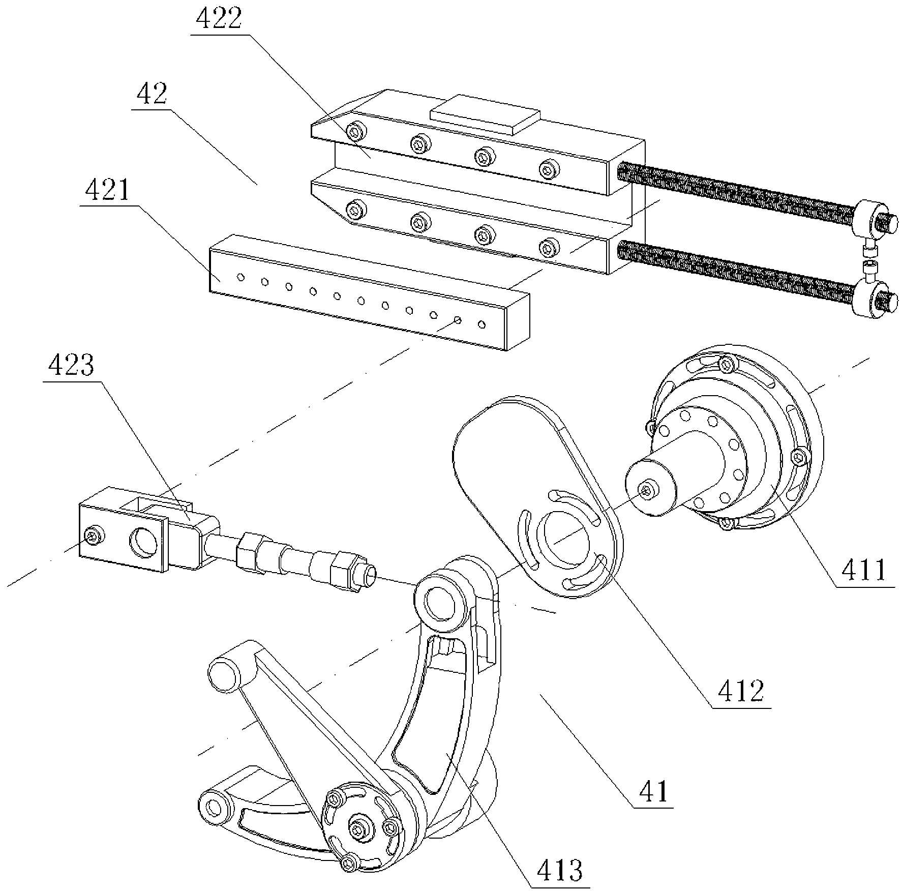
[0024] Such as Figure 1 to Figure 8 As shown, a heat pipe bending machine described in this embodiment includes a machine base 1, a feeding device 3 and a bending device 2 arranged on the machine base 1, wherein the upper part of the machine base 1 is provided with a vertical seat plate 11, The feeding device 2 is arranged behind the vertical seat plate 11, and the front of the vertical seat plate 11 is provided with a plurality of transmission connection mechanisms 4, and the bending device 2 is selectively installed on these transmission connection mechanisms 4, so the bending can be changed as required. The installation position of the bending device 2, so as to realize that the heat pipe 6 can be bent into different shapes to meet the different needs of customers, without modification, and has strong applicability. There is a motor in the base 1, and the feeding device 3 is driven by the motor. The heat pipe 6 is sent to the front end of the vertical seat plate 11, and th...


PUM


Abstract

The invention provides a heat pipe bending machine. The heat pipe bending machine comprises a baseframe, a feeding device and a bending device, and is characterized in that a vertical seat board is arranged at the upper part of the baseframe; the feeding device is arranged behind the vertical seat board; a plurality of transmission connection mechanisms are arranged in front of the vertical seat board; the bending device is selectively mounted on the transmission connection mechanisms, so that a heat pipe can be bent into different shapes to meet the customer demands and to achieve strong applicability; and a motor is arranged in the baseframe and used for driving the feeding device to convey the heat pipe to the front end of the vertical seat board and further driving the transmission connection mechanism to act so as to bend the heat pipe via the bending device, so that the heat pipe can be repeatedly bent into the required shapes in one-step transportation. The heat pipe bending machine achieves automatic control of the whole process, is high in machining precision, and is provided with a control device used for controlling the reducing direction of the heat pipe, so that the two reducing ends of the bent heat pipe face to the inner side, accordingly, unified and attractive appearance is obtained, and customer demands are met. The heat pipe bending machine is widely applied to the heat pipe bending technology.

Description

technical field [0001] The invention relates to an accessory of a heat pipe bending machine, in particular to a heat pipe bending machine. Background technique [0002] At present, the widely used heat transfer element is the heat pipe, which makes full use of the principle of heat conduction and the rapid heat transfer properties of the refrigeration medium, and quickly transfers the heat of the heating object to the heat source through the heat pipe, and its heat conduction capacity exceeds that of any known metal. thermal conductivity. In order to improve the heat transfer performance, heat pipes are generally bent into a certain arc shape. The current bending method of heat pipes is mainly manual operation. It is difficult to control the force during manual bending, and the rate of defective processing is relatively high. High, which increases the consumption of raw materials and consumes more human resources, which affects production efficiency. There are a few that u...

Claims


Application Information

Patent Timeline
IPC IPC(8): B21D7/024B21D43/08
Inventor 游本俊
Owner 游本俊
Learn More