Programmable Gain Isolation Amplifier Circuit and Its Realization Method
A technology of isolating amplifying circuits and programming gains, applied in gain control, amplifying control, electrical components, etc., can solve problems such as slow speed, poor small signal linearity, and the inability of continuously variable gain of amplifying circuits.
- Summary
- Abstract
- Description
- Claims
- Application Information
AI Technical Summary
Problems solved by technology
Method used
Image
Examples
Embodiment 1
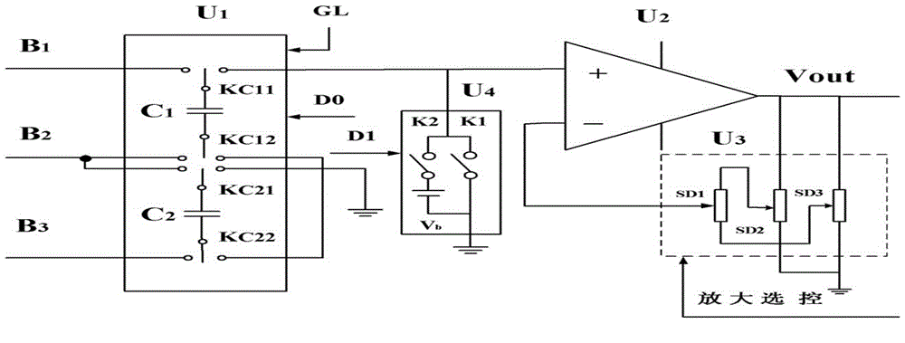
[0043] Embodiment 1: The signal sent by the signal conversion unit is a non-thermal resistance signal.
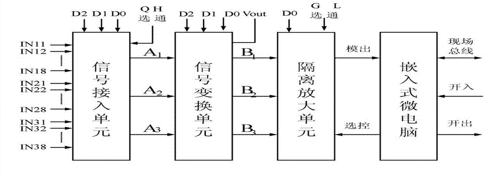
[0044] Such as figure 2 shown, the isolation unit U 1 Including input terminals B1, B2 and B3, conversion capacitors C1 and C2, microelectronic digital switch groups KC11, KC12, KC21 and KC22, strobe signal GL, control signal D0 of microelectronic digital single-pole double-throw switch, when strobe isolation unit U1 When the signals sent by the signal conversion unit are non-thermal resistance signals, they are all connected by the input terminals B1 and B2 of the strobe isolation unit U1, and the terminals B2 and B3 have no signal input at this time. At this time, the embedded microcomputer sends a low-level signal to the control signal D0 of the microelectronic digital single-pole double-throw switch, so that KC11, KC12, KC21, and KC22 are all on the left, and the conversion capacitors C1 and C2 are in the state of receiving signals , and then give a high-level signal...
Embodiment 2
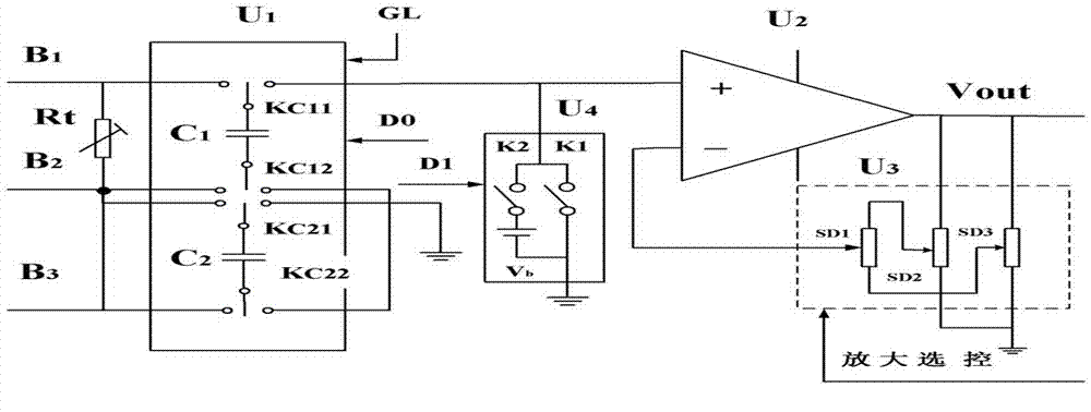
[0049] Embodiment 2: The signal sent by the signal conversion unit is a thermal resistance signal.
[0050] Such as image 3 As shown, when the isolation unit U1 receives the signal sent by the signal conversion unit as a thermal resistance signal, the input terminals B1 and B2 are connected to the thermal resistance Rt, and the terminals B2 and B3 are connected to the lead wire of the thermal resistance Rt, because the thermal resistance is used to measure When the temperature is high, the voltage drop on the wire should be deducted. The working process when measuring temperature with thermal resistance is: make the microelectronic digital switch group KC11, KC12, KC21, KC22 all close to the left, and the conversion capacitor C1 receives the voltage Vc1 on the thermal resistance Rt (上+,下-) , conversion capacitor C2 receives thermal resistor Rt lead voltage V 引线(上+,下-) , when the microelectronic digital switch groups KC11, KC12, KC21, KC22 are all on the right side, the uppe...
PUM
 Abstract
Description
Claims
Application Information
 - R&D
- Intellectual Property
- Life Sciences
- Materials
- Tech Scout
- Unparalleled Data Quality
- Higher Quality Content
- 60% Fewer Hallucinations
Browse by: Latest US Patents, China's latest patents, Technical Efficacy Thesaurus, Application Domain, Technology Topic, Popular Technical Reports.
© 2025 PatSnap. All rights reserved.Legal|Privacy policy|Modern Slavery Act Transparency Statement|Sitemap|About US| Contact US: help@patsnap.com


