
Real-time multi-DSP (digital signal processor) debugging system for signal processor system

A signal processor and debugging system technology, which is applied in the direction of electrical digital data processing, instruments, program control devices, etc., can solve the problems of increased cost and high price of DSP simulators, and achieves low cost, good real-time performance and high data transmission rate. Effect

Active Publication Date: 2013-07-24
INST OF ACOUSTICS CHINESE ACAD OF SCI
View PDF2 Cites 17 Cited by
  • Summary
  • Abstract
  • Description
  • Claims
  • Application Information

AI Technical Summary

Problems solved by technology

The higher price of a dedicated DSP emulator increases the cost significantly

Method used


Image

  • Real-time multi-DSP (digital signal processor) debugging system for signal processor system
  • Real-time multi-DSP (digital signal processor) debugging system for signal processor system
  • Real-time multi-DSP (digital signal processor) debugging system for signal processor system

Examples


Embodiment Construction

[0028] In order to make the object, technical solution and advantages of the present invention more clear, the present invention will be further described in detail below in conjunction with the accompanying drawings and embodiments. It should be understood that the specific embodiments described here are only used to explain the present invention, not to limit the present invention.

[0029] Below in conjunction with accompanying drawing, the present invention is described in detail.

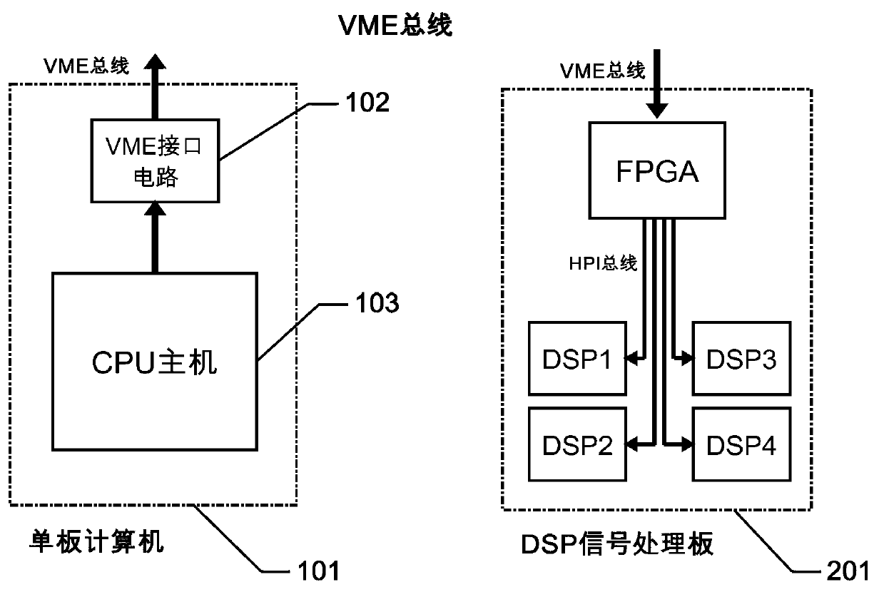
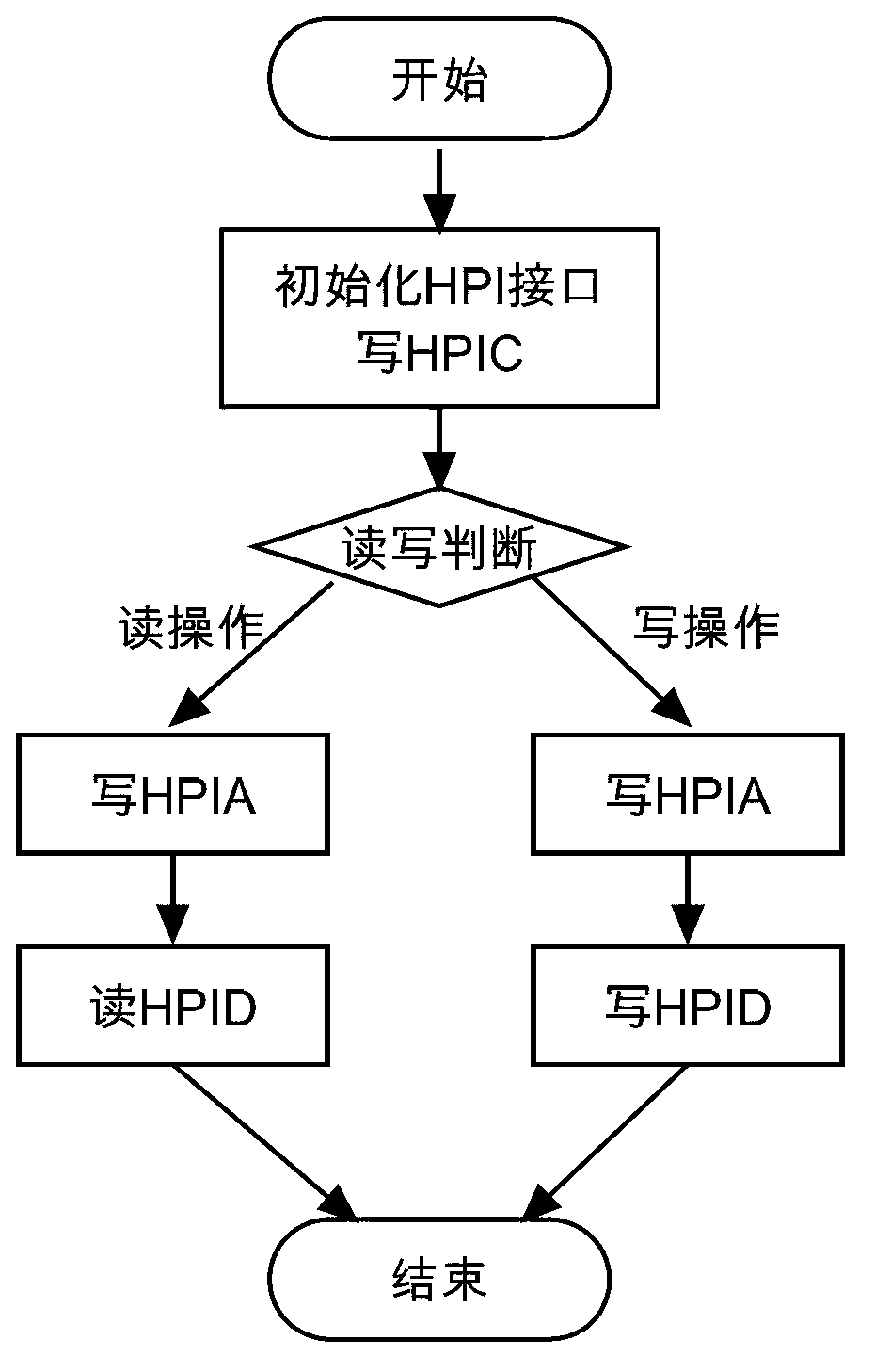
[0030] see figure 2 , The real-time multi-DSP debugging system of the signal processor system proposed by the present invention is composed of a single-board computer 101, a DSP signal processing board 201 and other boards. Wherein, the single-board computer 101 is a master device, and other boards are slave devices. The real-time multi-DSP debugging technology proposed by the present invention is to utilize the single-board computer 101 to transmit the DSP program to the DSP signal processi...


PUM


Abstract

The invention discloses a real-time multi-DSP (digital signal processor) debugging system for a signal processor system. The real-time multi-DSP debugging system for the signal processor system mainly comprises a single board computer, a DSP signal processing board and other board cards, wherein the single board computer is the main equipment of the signal processor, has the functions of control, display and data storage and can be communicated with other board cards of the signal processor via a VME (versa modular eurocard) bus; the DSP signal processing board is the slave equipment of the signal processor, is used for realizing abundant signal processing algorithms and mainly consists of a plurality of DSPs and FPGAs (field programmable gate array) modules; the single board computer transmits the DSP program to the DSP signal processing board via the VME bus; and the program is loaded to each DSP via an HPI (host port interface) bus by the FPGA module on the signal processing board. According to the technical scheme provided by the invention, the DSP program can be debugged in real time without interrupting the program operation, and the data transmission rate can reach hundreds of MB (mega byte) / s with a method that the DSP is debugged by an HPI interface. Compared with the traditional debugging method, the real-time multi-DSP debugging system for the signal processor system is improved by one order of magnitude, and a plurality of DSPs of a plurality of board cards can be simultaneously debugged.

Description

technical field [0001] The invention relates to the field of development and design of a general array signal processor, in particular to a technique for debugging and program loading by multiple DSPs. Background technique [0002] Signal processor systems are widely used in radar, sonar and other fields. Since the 1990s, DSP began to replace general-purpose processors as the main processing unit, and was widely used in signal processor systems. With the development of signal processing technology, complex algorithms have higher and higher requirements on the computing power and real-time performance of signal processors. Signal processors are constantly innovating, with larger scales and more and more integrated DSPs. [0003] The traditional DSP debugging method is to connect the DSP board to the PC host through a dedicated emulator for debugging and program loading, such as figure 1 shown. The emulator is a device used to realize hardware simulation, which can control ...

Claims


Application Information

Patent Timeline
Patent Type & Authority Applications(China)
IPC IPC(8): G06F13/40G06F9/445
Inventor 鄢社锋马晓川李宾杨力秦博彭承彦
Owner INST OF ACOUSTICS CHINESE ACAD OF SCI
Learn More