Stand pole and floating bridge adjusting structure, and floating dock applying stand pole and floating bridge adjusting structure

A technology for adjusting structures and floating docks, applied in the field of floating docks, can solve problems such as easy wear and tear of the coating, reduce the service life of floating docks, etc., and achieve the effect of reducing potential safety hazards

Inactive Publication Date: 2013-07-24
ZHEJIANG OCEAN UNIV
View PDF6 Cites 9 Cited by
  • Summary
  • Abstract
  • Description
  • Claims
  • Application Information

AI Technical Summary

Problems solved by technology

Although the floating pier relies on the pulley of the sliding device to be in close contact with the positioning pile, it can ensure that the floating pier is transmitted in multiple directions and disperses the force when it is impacted by waves and the water level rises and falls, and makes the floating pier move up and down flexibly. It can reduce the impact of the floating bridge on the fixed piles. However, under the frequent impact of the sea tide on the pulleys, the seawater corrosion-resistant coating on the surface of the fixed piles is easy to wear and fall off, thereby reducing the service life of the floating dock

Method used


Image

  • Stand pole and floating bridge adjusting structure, and floating dock applying stand pole and floating bridge adjusting structure
  • Stand pole and floating bridge adjusting structure, and floating dock applying stand pole and floating bridge adjusting structure
  • Stand pole and floating bridge adjusting structure, and floating dock applying stand pole and floating bridge adjusting structure

Examples


Embodiment 1

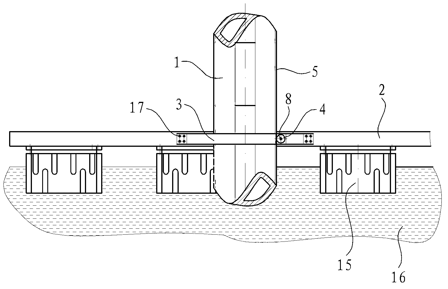
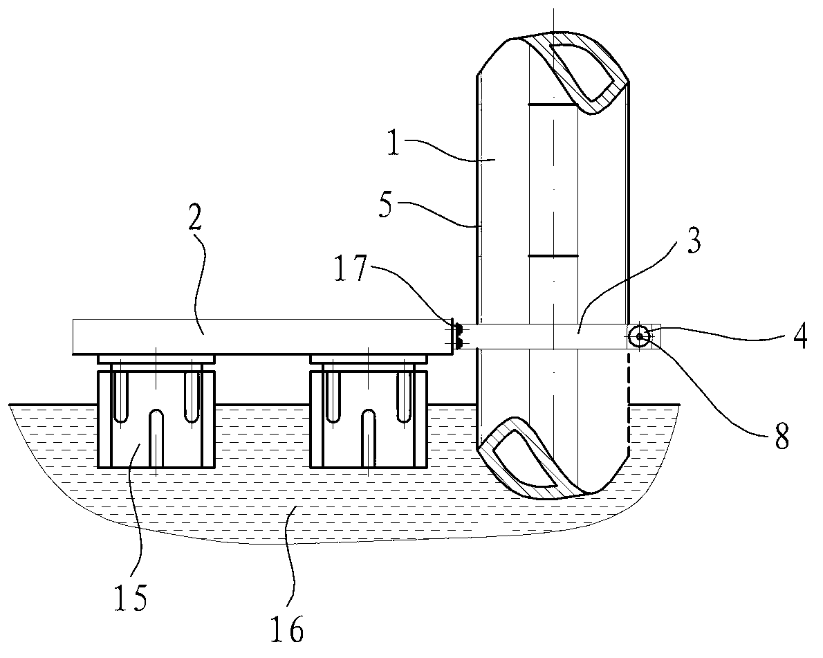
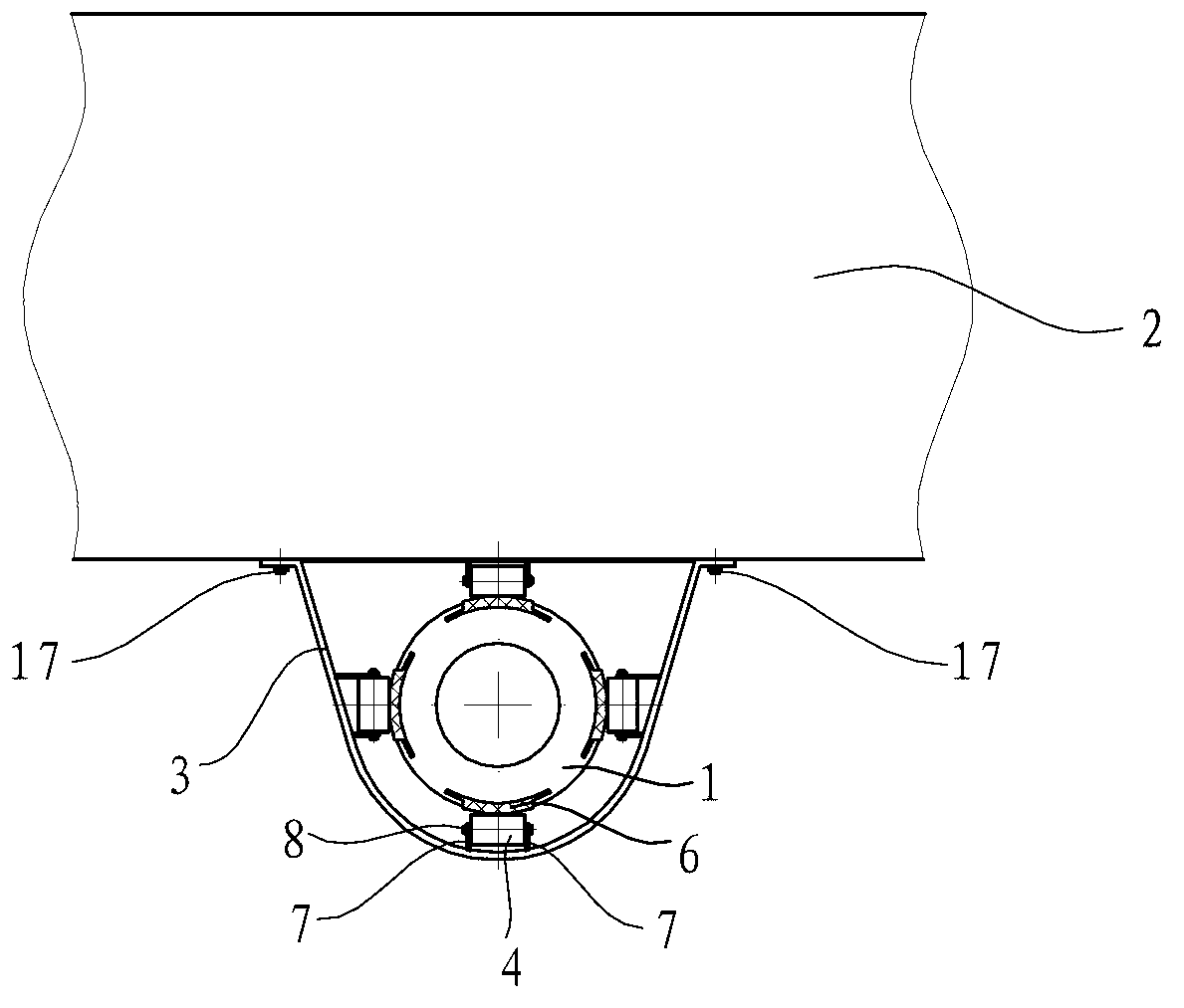
[0049] Embodiment one: if Figure 10 to Figure 14 As shown, the floating wharf in this embodiment includes components such as upright piles 1, auxiliary upright piles 10, pontoon bridge 2 and connecting channel 9, wherein the upright piles 1 and auxiliary upright piles 10 are all arranged on the seabed and exposed to the sea surface, and the pontoon bridge 2 is an integral skeleton formed by connecting multiple unit frames in series or in parallel, each unit frame adopts angle steel or I-beam as a welded component, and the floating bridge 2 and the vertical pile 1 are provided with the adjustment given in the above embodiment structure. A bridge deck is installed above the pontoon 2 to form a pontoon bridge deck, and a pontoon 15 is installed below the pontoon 2 , and the yacht 18 is parked on the mooring sea surface near the pontoon 2 . In order to prevent the wharf from being eroded by seawater and sea breeze, the surface of the unit frame is brushed with a coating resistan...

Embodiment 2

[0051] Embodiment two: if Figure 15 to Figure 20 As shown, the difference between the floating pier in this embodiment and the floating pier in Embodiment 1 lies in the connection channel. In this embodiment, the connecting channel 9 includes a fixed section 91 and a movable section 92, wherein the fixed section 91 is erected between the coast 11 and the auxiliary pile 10, the upper end of the movable section 92 is hinged with the fixed section 91, and the movable section 92 The lower end is slidingly connected on the floating bridge 2 . Specifically, the movable section 92 specifically includes components such as an upper beam frame 92a, a lower beam frame 92b, a step pedal 92c, a first pulley 92d, and a second pulley 92e. There are two upper beam frames 92a, which are parallel to each other and obliquely arranged on both sides of the connecting passage 9, and the top of the upper beam frame 92a is hinged with the fixed section 91 erected at the end of the auxiliary pile 10...


PUM


Abstract

The invention discloses a stand pole and floating bridge adjusting structure, which comprises a stand pole and a floating bridge, wherein the stand pole is arranged at the bottom of a sea and exposes out of the surface of the sea; the floating bridge floats on the surface of the sea; a positioning ring arranged on the periphery of the stand pole is fixed on the floating bridge; and the positioning ring is provided with a buffer wheel which can slide along the stand pole up and down. The stand pole and floating bridge adjusting structure is characterized in that an axial positioning groove is arranged outside the stand pole; a buffer sheet is wedged into the positioning groove; and the buffer wheel slides on the buffer sheet up and down. The invention also discloses a floating dock. The stand pole and floating bridge adjusting structure and the floating dock provided by the invention have the advantages that the buffer sheet wedged into the stand pole positioning groove can be used for absorbing energy that sea tides are bad for the floating bridge; when in ebb and flow of the tides, a pulley wheel arranged on the positioning ring can slide on the buffer sheet, so that hard impact and hard friction can be prevented from being generated; and no matter the ebb or the flow of the tides, a step plane of a channel connected with the floating dock always keeps parallel to a horizontal plane nearly, so that potential safety hazards of personnel working on the floating dock are reduced.

Description

technical field [0001] The invention relates to a floating wharf, in particular to an adjustment structure of upright piles and floating bridges in the floating wharf and a floating wharf using the adjustment structure. Background technique [0002] With the gradual reduction of domestic coastal production resources due to offshore production, coastal fishermen are adapting to the development of the new situation, sharing the fruits of development and seizing development opportunities. Yachts are gradually entering the lives of ordinary people in China. more and more. Among them, the floating marina is more common. This floating marina generally includes fixed piles and a floating bridge skeleton. The floating bridge skeleton is positioned on the fixed piles and can move up and down relative to the fixed piles with the ebb and flow of the tide. However, Due to the lack of good positioning between the existing floating bridge skeleton and the fixed piles, the ability to abso...

Claims


Application Information

Patent Timeline
IPC IPC(8): E02B3/06E01D15/24
Inventor 黄添彪谢永和马志军
Owner ZHEJIANG OCEAN UNIV
Why Eureka
Try Eureka