
Belt cleaner

A cleaner and belt technology, which is applied in the direction of cleaning devices, transportation and packaging, conveyor objects, etc., can solve the problems of cleaning head wear, long downtime, time-consuming and labor-intensive, etc., to achieve convenient long-term use, no damage to the belt, and long service life long effect

Inactive Publication Date: 2013-07-17
芈鑫
View PDF7 Cites 6 Cited by
  • Summary
  • Abstract
  • Description
  • Claims
  • Application Information

AI Technical Summary

Problems solved by technology

[0003] In order to solve the material adhesion phenomenon of the belt conveyor, technicians install a cleaner under the power roller of the belt conveyor head. In order to ensure the cleaning effect, it is necessary to ensure that the cleaning head of the cleaner is in elastic contact with the belt on the roller. In the actual use process, the cleaning head wears quite seriously. How to ensure the elastic contact between the cleaning head and the drum belt after the cleaning head is worn is a difficult problem. Most of the belt cleaners on the market currently use high-strength springs to ensure that this belt cleaner is installed. The process is time-consuming and labor-intensive, requiring multiple people to operate at the same time. Moreover, the service life of the belt cleaner is short. When the cleaning head is severely worn, the contact between the cleaner and the belt cannot be guaranteed. The entire cleaner must be disassembled, and the cleaning head and scraper plate must be replaced. It is integrated with the rotating shaft and the scraping plate cannot be adjusted up and down. When the upper part of the scraping plate is worn, it cannot scrape the material. It is necessary to replace the entire scraping device including the rotating shaft, resulting in longer downtime and affecting the conveying efficiency of the conveyor.

Method used


Image

  • Belt cleaner
  • Belt cleaner
  • Belt cleaner

Examples


Embodiment Construction

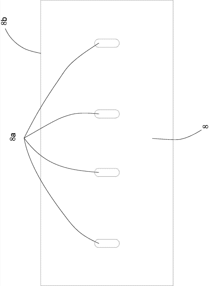
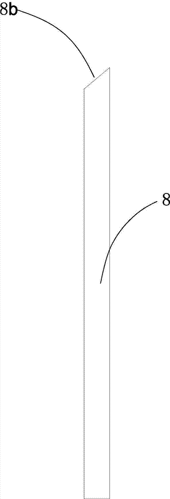
[0018] Such as Figures 1 to 2 As shown, the scraper 8 is a rectangular ultra-high molecular weight polyethylene plate with a thickness of 10mm (molecular weight of more than 3 million). There are four locking through holes 8a in the middle of the scraper 8, and the locking through holes 8a are waist-shaped Through hole, scraper plate 8 rear end has the scraper end surface 8b that contacts with belt 10 on the outer wall of belt drum 3 .

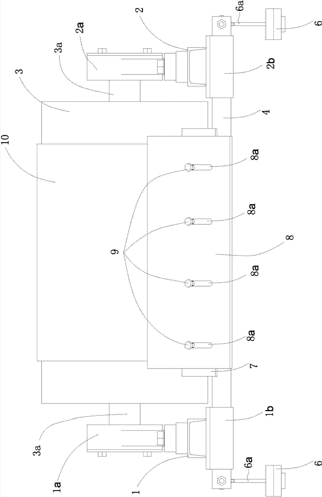
[0019] Such as Figures 3 to 5 As shown, the horizontally arranged left bracket 1 is fixed with a first bearing seat 1a by bolts, and the horizontally arranged right bracket 2 is fixed with a second bearing seat 2a by bolts. The left bracket 1 and the right bracket 2 are coplanar and parallel, and the belt pulley 3 A roller shaft 3a is installed in the axial direction, and the two ends of the roller shaft 3a are respectively matched with the first bearing seat 1a and the second bearing seat 2a, and a belt 10 is attached to the outside of the...


PUM


Abstract

The invention provides a belt cleaner which comprises a scraper. The scraper is fixed onto a rotary shaft, the rotary shaft is fixedly connected with adjusting mechanisms, the adjusting mechanisms comprise connecting rods, front ends of the connecting rods are fixedly connected with the rotary shaft along the radial direction of the rotary shaft, and balancing weights are connected to rear ends of the connecting rods. During usage, the cleaner is fittingly fixed to the front of a rotary drum of a belt conveyor, the balancing weights drive the rotary shaft to rotate by the lever principle, the rotational angle of the rotary shaft is adjusted by means of increasing or reducing the balancing weights, the scraper applies pressure in the direction of the belt, and an effect of pressing the scraper with the belt is realized; and when the belt moves along the peripheral direction of the rotary drum of the belt, the scraper scratches foreign matters on the surface of the belt, and an effect of cleaning the foreign matters on the surface of the belt is realized.

Description

technical field [0001] The invention relates to a belt cleaner. Background technique [0002] During the process of conveying materials, some materials will adhere to the surface of the belt, especially in coke, coal and other fields. The phenomenon of material adhesion on the surface of the belt is particularly serious. The weight increases the energy output of the belt conveyor, resulting in a waste of energy. At the same time, it reduces the actual conveying capacity of the belt conveyor, reduces the conveying efficiency, and causes waste of conveyed materials. [0003] In order to solve the material adhesion phenomenon of the belt conveyor, technicians install a cleaner under the power roller of the belt conveyor head. In order to ensure the cleaning effect, it is necessary to ensure that the cleaning head of the cleaner is in elastic contact with the belt on the roller. In the actual use process, the cleaning head wears quite seriously. How to ensure the elastic contac...

Claims


Application Information

Patent Timeline
Patent Type & Authority Applications(China)
IPC IPC(8): B65G45/12
Inventor 曹晓红张奎芈鑫
Owner 芈鑫
Learn More