
Fault diagnosis method based on code bit mapping model

A mapping model and fault diagnosis technology, applied in special data processing applications, instruments, electrical digital data processing, etc., can solve the problems of many data packets, large transmission bandwidth, poor configurability, etc., to achieve simple message structure, configurable High configurability and bandwidth saving effect

Active Publication Date: 2013-07-10
CASCO SIGNAL
View PDF4 Cites 4 Cited by
  • Summary
  • Abstract
  • Description
  • Claims
  • Application Information

AI Technical Summary

Problems solved by technology

[0003] According to the type of information, the signal system maintenance data is mainly divided into three categories: alarm quantity, state quantity and analog quantity. The current maintenance information communication interface protocol mainly has the following definition methods: First, different types of data are grouped and sent separately , there are many data packets, and the sending and receiving parties consume a lot of resources; the second method is to send the maintenance information in plaintext packets. This method has a large amount of information and is easier to parse, but because the data packets are generally large, the transmission occupies more bandwidth. ; The third is to define the maintenance information through the fault code, the message is simple, but not comprehensive
Moreover, the definition of maintenance data is relatively fixed in terms of data structure, and the configurability is poor. If the maintenance data increases or decreases, it will bring about large changes.

Method used


Image

  • Fault diagnosis method based on code bit mapping model
  • Fault diagnosis method based on code bit mapping model
  • Fault diagnosis method based on code bit mapping model

Examples


Embodiment

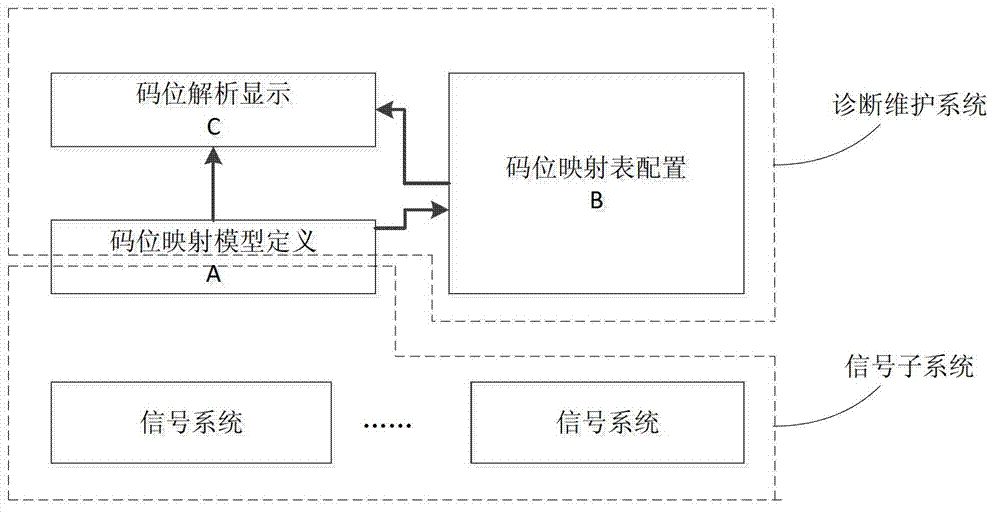
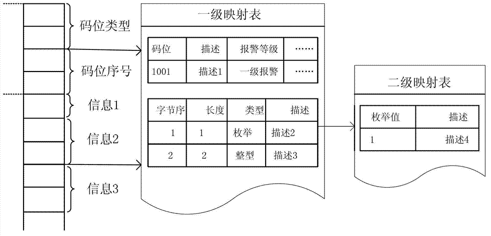
[0026] Such as figure 1 As shown, a fault diagnosis method based on the code point mapping model, according to the code point mapping model, the diagnosis and maintenance system analyzes the fault information sent by the information subsystem, so as to diagnose and maintain the fault. The diagnosis and maintenance system includes Mapping table storage module and code point analysis and display module, the main method includes code point mapping model definition A, code point mapping table configuration B, code point analysis display C three parts, wherein code point mapping table configuration B and code point analysis display C Both rely on the code point mapping model definition A, and the code point analysis shows that C will use the output file of the code point mapping table configuration B.

[0027] Such as image 3 As shown, this method has been applied in the rail transit trackside safety platform diagnosis and maintenance system, combined with this example, the speci...


PUM


Abstract

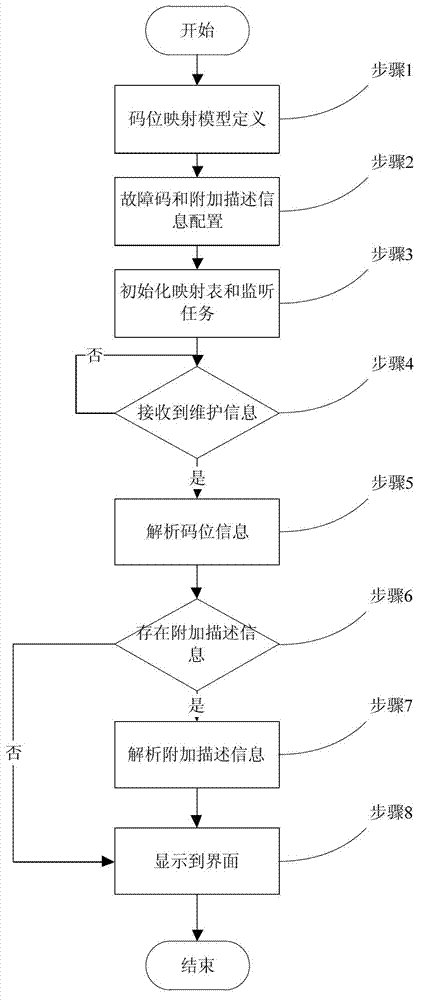
The invention relates to a fault diagnosis method based on a code bit mapping model. The fault diagnosis method comprises the following steps: defining a code bit mapping model between an information subsystem and a diagnosis maintenance system; configuring all fault information and storing all the fault information into a code bit mapping table of a mapping table storage module by the information subsystem; loading and initializing the code bit mapping table, starting a monitoring task thread and receiving the fault information sent by the information subsystem by a code bit analysis and display module; judging whether the fault information sent by the information subsystem is received, and if so, entering a next step, otherwise, keeping a monitoring state; analyzing the received fault information, and through recognition and comparison of the code bit mapping table, obtaining describing and warning information and maintenance information corresponding to the fault information; and displaying the analyzed describing and warning information and the analyzed maintenance information on an interface. Compared with the prior art, the fault diagnosis method has the advantages of simple message structure, information comprehensiveness, high configurability and the like.

Description

technical field [0001] The invention relates to a rail transit fault diagnosis method, in particular to a fault diagnosis method based on a code bit mapping model. Background technique [0002] In various rail transit signal systems, diagnostic maintenance is one of the necessary functions. This function can actively or passively interact with other functional modules or other subsystems to realize the operation status, fault and Alarm monitoring. [0003] According to the type of information, the signal system maintenance data is mainly divided into three categories: alarm quantity, state quantity and analog quantity. The current maintenance information communication interface protocol mainly has the following definition methods: First, different types of data are grouped and sent separately , there are many data packets, and the sending and receiving parties consume a lot of resources; the second method is to send the maintenance information in plaintext packets. This met...

Claims


Application Information

Patent Timeline
Patent Type & Authority Applications(China)
IPC IPC(8): G06F19/00
Inventor 孙军峰张兵建董高云周庭梁寇文婧余文兵
Owner CASCO SIGNAL
Learn More