Optical interference gas detection system with air pressure balance device

A gas detection system and air pressure balance technology, which are used in measurement devices, phase influence characteristic measurement, material analysis by optical means, etc., can solve the problems of interference fringe change, difficult processing, difficult to achieve, etc., and meet the requirements of reducing high precision , High measurement accuracy, and the effect of improving the durability level

Inactive Publication Date: 2015-10-28
重庆一心仪器仪表有限公司
View PDF6 Cites 0 Cited by
  • Summary
  • Abstract
  • Description
  • Claims
  • Application Information

AI Technical Summary

Problems solved by technology

In addition, during use, the slight displacement of the light source and / or the degumming of the glued surface will cause a huge change in the interference fringes, which will affect the accuracy of the measurement results, so there are disadvantages of high manufacturing cost and poor stability
[0005] The utility model patent with the application number 2011204170.0 of the same applicant as the present invention discloses an intelligent optical interference gas measuring device, which uses an optical slit to divide the light emitted by the light source into two beams a and b, and then passes through the gas chamber The partition divides the light beam a into a1 and a2, and then a1 and a2 return to the plane beam splitter through the reflection of the refracting rectangular prism respectively, and interfere with the light beam b, although the error caused by the temperature, pressure and mechanical mechanism of the device is Effective suppression, but because the narrow beam a is divided into two beams by the air chamber partition, the processing is difficult, and the precision of the equipment is high, so it is difficult to realize; and when the temperature difference becomes larger, the measured interference fringe shadow becomes Coarse, affecting the measurement results and accuracy; and the deformation of the interference fringes will also cause a large difference between the measurement results and the real value; the device cannot be used in the measurement environment for a long time

Method used


Image

  • Optical interference gas detection system with air pressure balance device
  • Optical interference gas detection system with air pressure balance device
  • Optical interference gas detection system with air pressure balance device

Examples


Embodiment Construction

[0015] A non-limiting embodiment is given below in conjunction with the accompanying drawings to further illustrate the present invention.

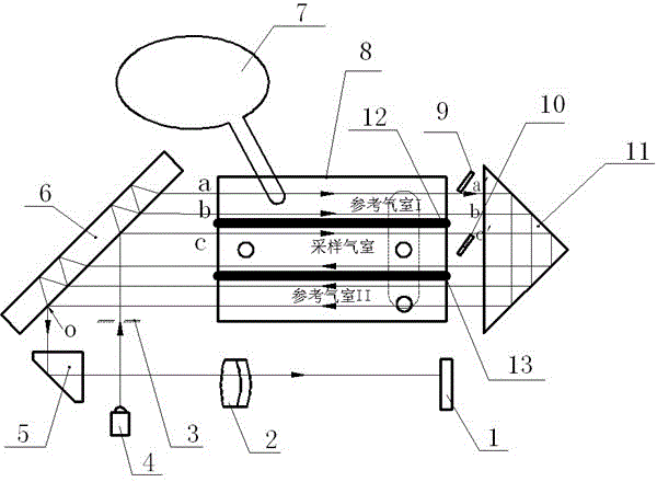
[0016] refer to figure 1 As shown, an optical interference gas detection system with an air pressure balance device includes a light source 4, a plane beamsplitter 6, an air chamber 8, a refractive right-angled prism 11, a reflective right-angled prism 5, an image sensor 1 and a light beam consisting of several optical elements. The interference optical path system is characterized in that it also includes a closed pressure balance device 7, wherein the pressure balance device 7 communicates with the air chamber 8;

[0017] On the optical path of the light source 4, the plane beam splitter 6 installed at 45° divides the light beam emitted by the light source 4 and passing through the light slit 3 into parallel beams a, b and c;

[0018] The incident end of the air chamber 8 corresponds to the 45° face of the plane beamsplitter 6, and its...


PUM


Abstract

The invention provides a novel optical interference gas test optical path system and an air pressure balance device. According to the pressure-sensitive optical interference principle design, through a light source, a beam of light is divided into three light beams under the action of a plane spectroscope by a plurality of optical elements such as an image sensor, a plane spectroscope and the like to form two groups of optical interference fringes, and the two groups of optical interference fringes are processed to obtain a measurement result. The novel air pressure balance device is of a sealed type structure, so that the requirement on long-time work in the use environment can be met. The invention aims at providing the optical interference gas test optical path system and the air pressure balance device, which are high in precision, simple to manufacture, and balanced in pressure.

Description

technical field [0001] The invention relates to an instrument characterized by optical measurement, in particular to an optical interference gas detection system with an air pressure balance device utilizing the principle of optical interference. Background technique [0002] The optical interference methane detector developed by Riken Corporation in Japan in the 1950s is the most widely used optical interference methane detector in the market. Its optical path and mechanical structure adopt the principle of Yamin optical interference, and the optical system is directly observed by the human eye through a negative lens. The methane concentration is measured by the amount of light interference fringes shifted. The reading of this optical interference methane detector depends on the reading of the human eye with a mechanical scale during use, and the error is large; the pressure balance uses a capillary, the pressure balance speed is slow, and it cannot be used in a working en...

Claims


Application Information

Patent Timeline
Patent Type & Authority Patents(China)
IPC IPC(8): G01N21/01G01N21/45
Inventor 陆飞夏飞李鹏君秦军政
Owner 重庆一心仪器仪表有限公司
Why Eureka
Try Eureka