Multifunctional turbofan jet engine

A technology of jet engines and turbofans, applied in the direction of machines/engines, jet propulsion devices, gas turbine devices, etc., can solve the problems of not being able to greatly increase and change speed, potential safety hazards, blade ablation, etc., to improve thermal management capabilities, Long service life and high thrust-to-weight ratio

Inactive Publication Date: 2013-07-10
魏汉章
View PDF6 Cites 11 Cited by
  • Summary
  • Abstract
  • Description
  • Claims
  • Application Information

AI Technical Summary

Problems solved by technology

Here are a few questions: 1. Is it true that the high temperature at the overlapping place of the tail flame of the flame tube will cause the blade to be ablated at an accelerated rate and this problem really cannot be solved? 2. How does the intake air enter the ring tube combustion chambers of the 8 flame tubes? 3. According to different requirements of thrust, how to let the intake air enter into the annular tube combustion chambers of dozens or even hundreds of flame tubes?
[0015] Existing aero-engines, whether turbojet or turbofan, whether domestic or foreign, are all large cylinders (combustion chambers), which not only have high temperature, high fuel consumption, small thrust, many parts, slow speed, and cannot be greatly improved. The problem of speed increase and speed change is more dangerous. There are potential safety hazards. Once the only large combustion chamber (big cylinder) of the engine fails, the machine will often be destroyed.

Method used


Image

  • Multifunctional turbofan jet engine
  • Multifunctional turbofan jet engine
  • Multifunctional turbofan jet engine

Examples


Embodiment Construction

[0043] At present, the existing Taihang and Kunlun aero-engines in China all use turbofan engines as prototypes.

[0044] Provide a non-limiting embodiment below in conjunction with accompanying drawing and further illustrate the present invention.

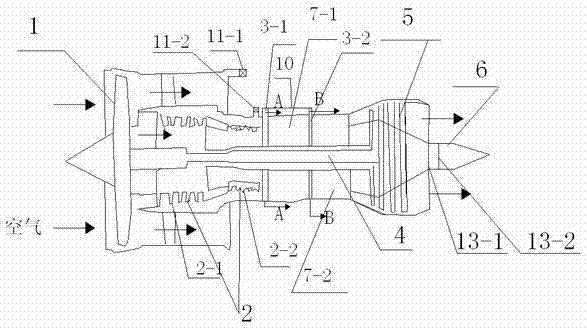
[0045] refer to figure 1 , figure 2 , image 3 , Figure 4 , Figure 5 and Figure 6 As shown, a multifunctional turbofan jet engine includes: a fan 1 for inhaling air, a compressor 2 for performing work on the inhaled air, and a second combustion chamber 7-2 for igniting the gas that has performed work through the compressor , the turbine 5 and the exhaust pipe 6 which discharges the combusted gas, and also includes the first combustion chamber 7-1 arranged at the intake end of the second combustion chamber 7-2, wherein the first combustion chamber 7-1 and the second combustion chamber 7-2 are provided with a tubular combustion cylinder 8; the cylindrical outer covers of the first combustion chamber and the second combusti...


PUM


Abstract

The invention discloses a multifunctional turbofan jet engine which includes a fan, a gas compressor, a second combustor, a turbine and an exhaust nozzle, wherein the fan is used for sucking air, the gas compressor is used for doing work on the sucked air, the second combustor is used for igniting gas on which the gas compressor does work, and the exhaust nozzle is used for exhausting the combusted gas. The multifunctional turbofan jet engine further comprises a first combustor, a first splitter plate and a second splitter plate, wherein the first combustor is arranged in front of the second combustor, the first splitter plate and the second splitter plate are used for splitting gas, the first splitter plate and the first combustor are correspondingly arranged, the second splitter plate and the second combustor are correspondingly arranged, and the first splitter plate and the second splitter plate are respectively provided with a travel switch I and a travel switch II which are used for rotating the corresponding splitter plate. The invention aims to provide the multifunctional turbofan jet engine which has the advantages of inlet air cooling, accurate gas splitting, balanced ignition, uniform-velocity starting, level-changing acceleration, high-efficiency, safety, thrust vectoring, easy operation and versatility.

Description

technical field [0001] The invention relates to the technical field of aerospace engines, in particular to a turbofan jet engine adopting multi-cylinder technology. Background technique [0002] Today's civil aviation aircraft can only fly to an area of ​​10 kilometers high; fighter jets generally fly to a height of about 20 kilometers, and it will be very difficult to fly higher. There are very few aircraft that can break through the height of 20 kilometers. Satellites cannot fly below 100 kilometers, because satellites orbiting the earth below 100 kilometers have no power, and the altitude drops to 100 kilometers from the ground, and the satellite will soon fall. At present, the adjacent space at an altitude of 20-100 kilometers is basically a blank area. All countries are now studying how to develop adjacent space vehicles. Whoever can break through and occupy this commanding height will have the air supremacy except space. To develop adjacent space vehicles, it is ne...

Claims


Application Information

Patent Timeline
Patent Type & Authority Applications(China)
IPC IPC(8): F02K3/00F02C7/141F23R3/42
Inventor 魏汉章魏欣
Owner 魏汉章
Why Eureka
Try Eureka