Electronic device with display

A technology for electronic equipment and display parts, which is applied to display devices, illuminated signs, light guides, etc., can solve the problems of reduced average light quantity, large influence, and increased number of used units, so as to reduce the number of used units, reduce assembly man-hours, Moderate the effect of spot light

Active Publication Date: 2013-07-03
ORMON CORP
View PDF8 Cites 1 Cited by
  • Summary
  • Abstract
  • Description
  • Claims
  • Application Information

AI Technical Summary

Problems solved by technology

[0019] However, when the diffusivity of the diffusion sheet 7 is strong, the transmittance of the light will be lowered instead, so that the average light quantity of the LED 9a illuminated to the LCD display 6 will decrease.
Furthermore, since the diffusion sheet 7 is made into a structure with strong diffusivity and low light transmittance, a plurality of sheets are stacked, and the cost of the diffusion sheet 7 becomes high. The added countermeasure and the spot light mitigation countermeasure are in a trade-off relationship, making the adjustment of the two difficult in design
[0020] Then, LED9a shines on the increase of the average light quantity of LCD display 6 and the balance of spotlight relaxation becomes restrictive conditions each other, and the installation number of LED9a increases proportionally with the expansion of the LCD area of ​​LCD display 6 to LCD display control substrate 9, must not no increase
In other words, high-brightness LEDs with high light intensity cannot be used, and it is difficult to reduce the number of LEDs used
As a result, the number of LEDs used increases, especially when the LCD display 6 is a large-scale display, its influence is large, and the restriction conditions for increasing the average light quantity and mitigating the spot light to achieve a balance are more stringent, and the use of LEDs is individual. The increase in the number has to become a bottleneck for the cost increase caused by the reduction of the number of parts of the drive circuit including LED9a and the reduction of power consumption.
[0021] In addition, in order to alleviate the speckle light, the distance between the LED 9a mounted on the LCD display control board 9 and the LCD display 6 is lengthened, and the LCD display 6 is kept away from the light source, that is, the LED 9a, for example, by increasing the thickness direction of the reflector 8. However, the result of this countermeasure is contrary to the important realization condition of the thermostat 1, namely miniaturization

Method used


Image

  • Electronic device with display
  • Electronic device with display
  • Electronic device with display

Examples


Embodiment Construction

[0066] The embodiments of the present invention are configured to simultaneously increase the average amount of light irradiated by the LED to the LCD display and alleviate the speckle light, and also fully meet the miniaturization requirements.

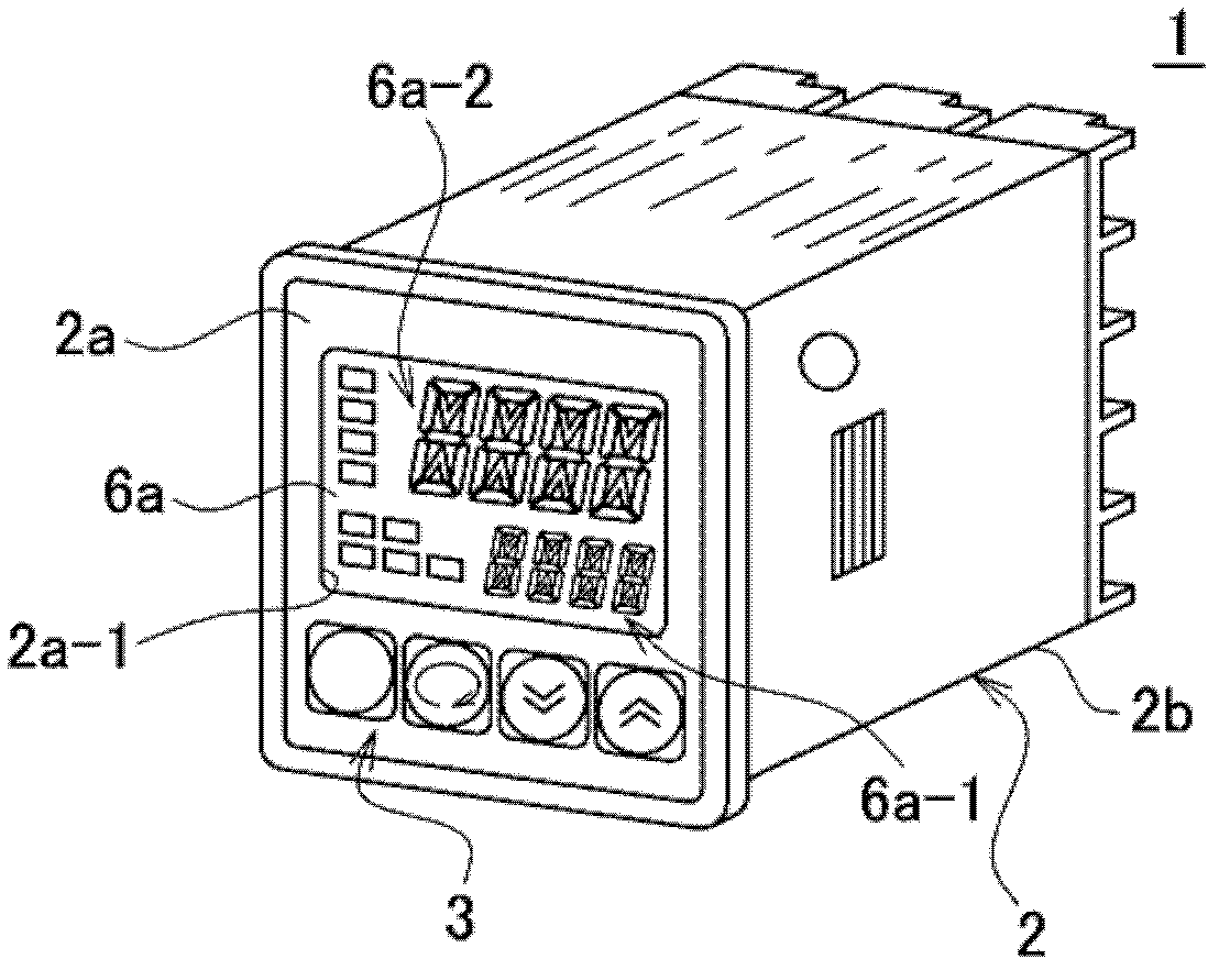
[0067] Hereinafter, one of the embodiments of the present invention will be described by assigning the same symbols to the configurations corresponding to the above-mentioned prior art, using the drawings. First, use figure 1 , the appearance structure of a general temperature regulator will be described. The temperature regulator 1 as an electronic device is configured such that a display area as a display unit for displaying a set temperature value and the like is arranged on the front part of the electronic device casing 2. 6a or a plurality of operation buttons 3 for operating a control unit and the like, and an LCD display unit 10 and the like which will be described later are accommodated in the electronic equipment case 2 .

...


PUM


Abstract

An LCD display unit (10) according to the present invention is constituted by an LCD display (6) including a display unit comprised of a set temperature display unit (6a-1) and a present temperature display unit (6a-2), a diffusion sheet (7) arranged on the rear surface side of the LCD display (6), a reflection frame body (8) arranged on the rear surface side of the diffusion sheet, a light guide plate (20) arranged on the rear surface side of the reflection frame body (8) such that the outer periphery portion is covered with the reflection frame body (8), and an LCD display control substrate (9) arranged on the rear surface of the light guide plate (20). An LED (9a) is mounted as a light source for the LCD display (6), for example, on the right side periphery portion on the front surface side of the LCD display control substrate (9) in order for the irradiation light from the LED (9a) to be incident onto the side wall surface portion (20a) of the light guide plate (20), and thus the LCD display unit is constituted such that the display portion of the LCD display (6) can be irradiated.

Description

technical field [0001] The present invention relates to an electronic device including a display unit such as a temperature regulator, a timer, or a digital panel meter. Background technique [0002] Usually, in this kind of electronic equipment, for example, when the current temperature of the temperature regulator reaches the prescribed temperature through the relationship of the set temperature set corresponding to the control temperature, the temperature control object is heated according to the prescribed control temperature. It is used to control the temperature of the workpiece, which is the object of temperature control, by turning ON or OFF the power supply of the heater. [0003] Such a thermostat is configured as an electronic device that uses a plurality of control panels installed on the side of the external device, and is composed of a control board constituting a control unit for controlling the external device, terminals electrically connected to the external...

Claims


Application Information

Patent Timeline
IPC IPC(8): G02F1/13357G02F1/1333
CPCG02B6/0051G02B6/0055G02F1/133615G02F2203/02G02F2203/22G02F1/1333G02F1/1335G09F13/04
Inventor 若林武志石田一人
Owner ORMON CORP
Why Eureka
Try Eureka