Two engine system with a gaseous fuel stored in liquefied form

A gaseous fuel, twin-engine technology, applied in the field of twin-engine systems

Active Publication Date: 2013-07-03
WESTPORT POWER
View PDF5 Cites 21 Cited by
  • Summary
  • Abstract
  • Description
  • Claims
  • Application Information

AI Technical Summary

Problems solved by technology

In addition, the auxiliary engine can replace the hydraulic system which is more complex and prone to maintenance problems, which leads to simplification of the overall system and increased reliability

Method used


Image

  • Two engine system with a gaseous fuel stored in liquefied form
  • Two engine system with a gaseous fuel stored in liquefied form
  • Two engine system with a gaseous fuel stored in liquefied form

Examples


Embodiment Construction

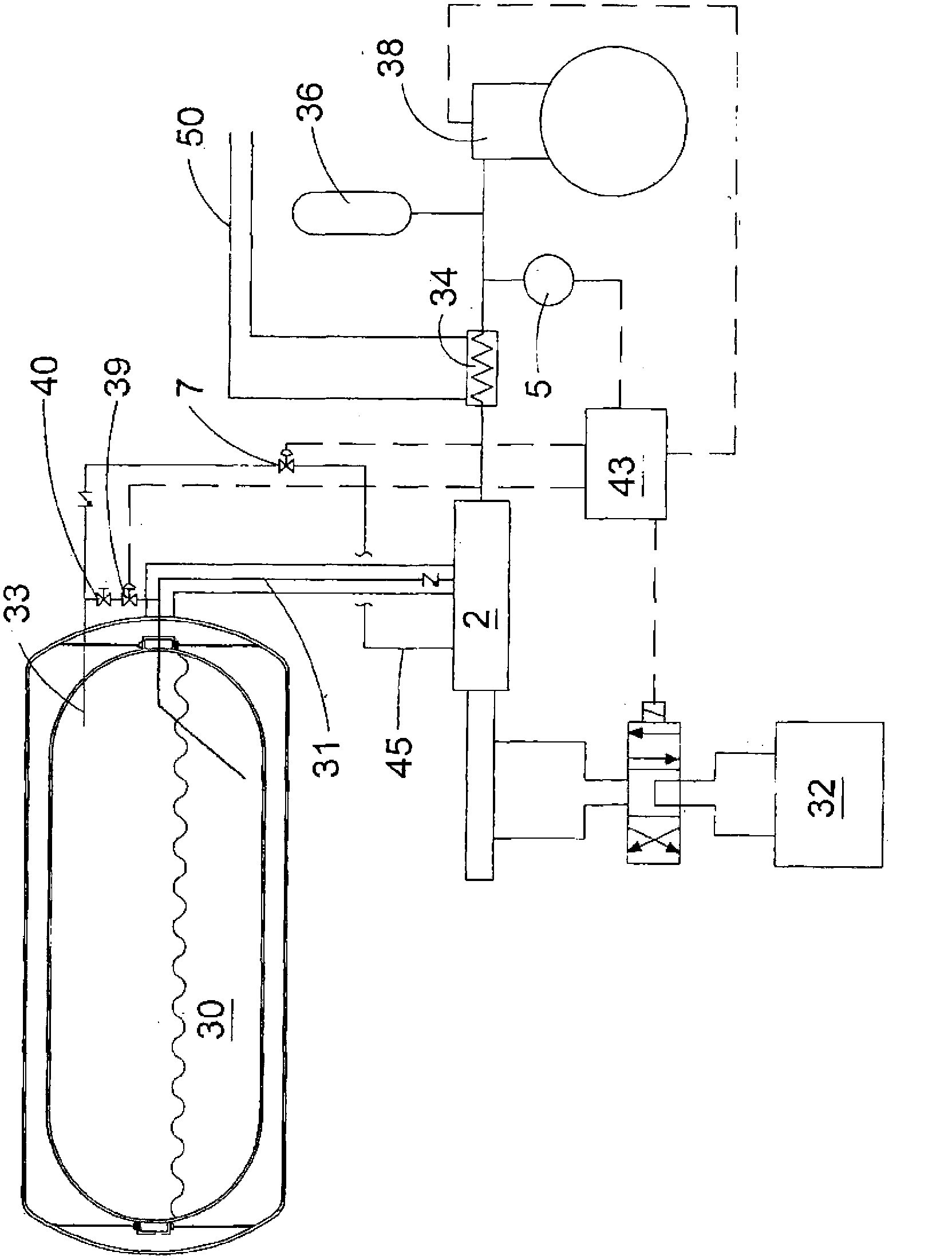
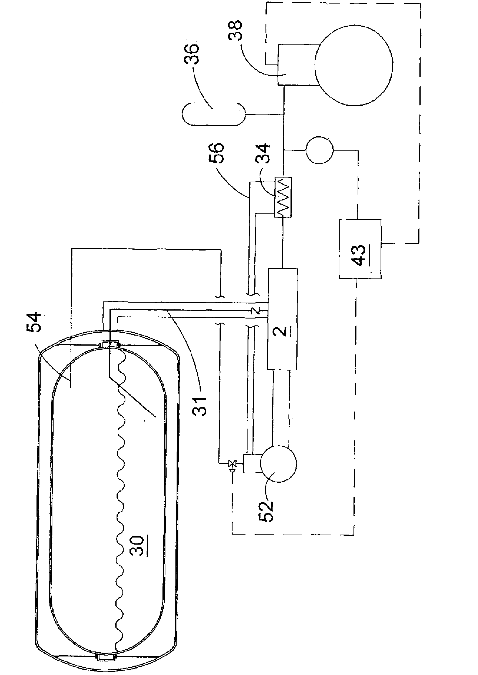
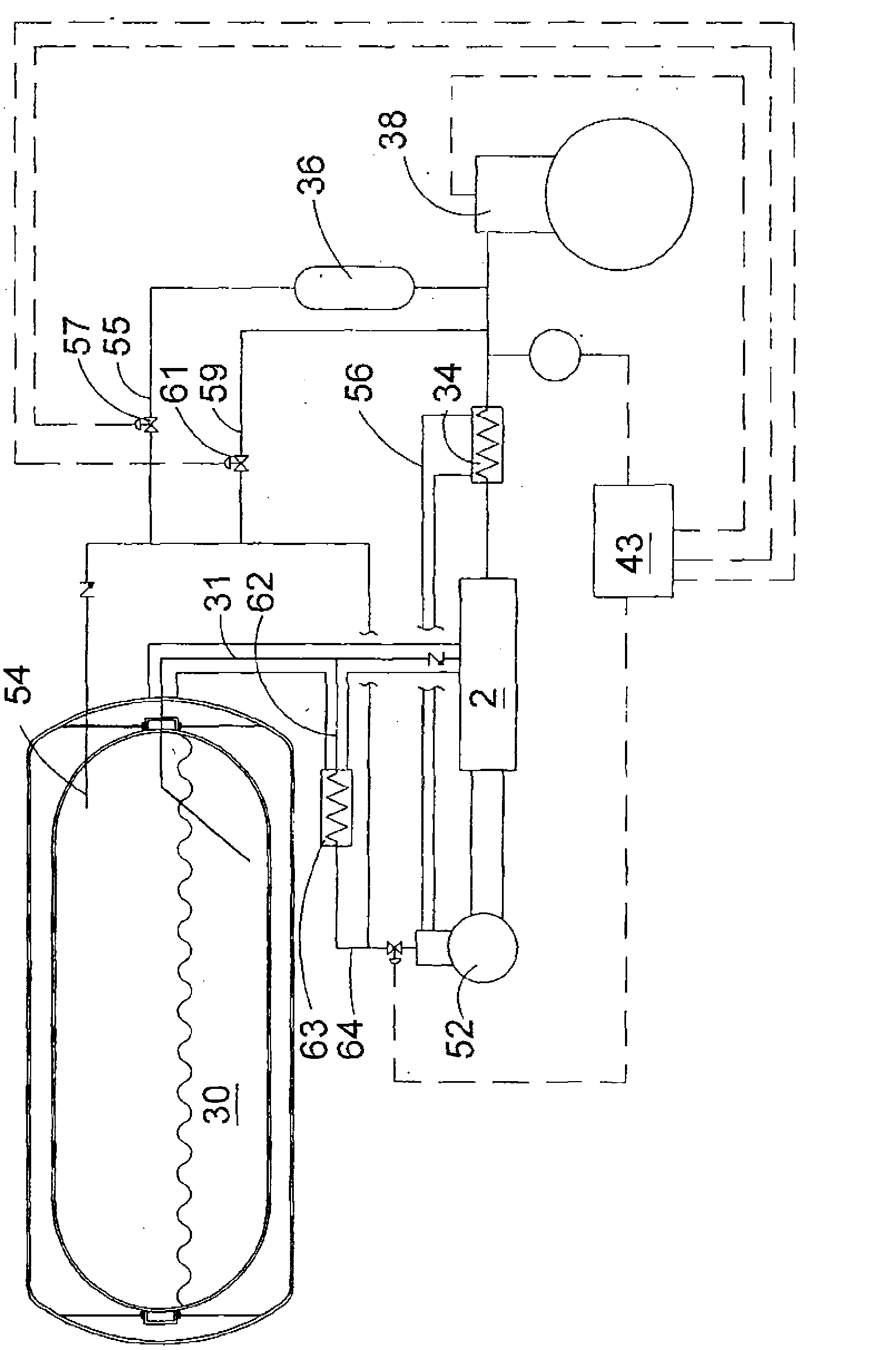
[0020] The disclosed twin engine system includes a fuel injected HPDI internal combustion engine for motoring purposes, wherein the fuel injected HPDI internal combustion engine is fueled by gaseous fuel stored on board the vehicle in liquid form. The fuel supply system converts the stored liquid gas into gaseous form and delivers it at injection pressure for direct injection into the combustion chamber of the HPDI internal combustion engine. For example, if the liquid gaseous fuel is natural gas, the storage pressure between about -130 degrees Celsius and -160 degrees Celsius is typically less than about 10 bar. Injection pressures for HPDI internal combustion engines are typically at least 200 bar. In a typical system, the pressure relief valve can be set at approximately 17 bar (approximately 250 psi). According to the disclosed system, a separate auxiliary fumigation internal combustion engine, also fueled by gaseous fuel, is used to drive the cryopump in the fuel supply ...


PUM


Abstract

A gaseous fuelled two engine system is disclosed comprising a high pressure direct injection engine as the main power source and an auxiliary fumigated engine that can be fuelled with vapor removed from a storage tank that stores the gaseous fuel in liquefied form at cryogenic temperatures. The fuel supply system comprises a cryogenic pump for raising the pressure of the fuel to the injection pressure needed for the high pressure direct injection engine, and the cryogenic pump is powered by the auxiliary fumigated engine.

Description

technical field [0001] The present invention discloses a twin engine system with gaseous fuel stored in liquid form. In a specific embodiment, the gaseous fuel is natural gas stored onboard the vehicle in liquid form at cryogenic temperatures. The disclosed methods and apparatus also relate to preventing release of boil-off gases to the atmosphere. Background technique [0002] The internal combustion engine has been used to generate power and drive machines for more than a century. Historically, gasoline and diesel have been the preferred fuel choices because they are plentiful, cheap and easy to store. Although natural gas has been used as a fuel for vehicles for more than five decades, widespread use has been limited for various reasons, including fuel storage density, infrastructure, fuel availability, and the differences with conventional Fuel-fed means of transport usually have higher capital costs. However, alternative fuel options are gaining attention due to fac...

Claims


Application Information

Patent Timeline
Patent Type & Authority Applications(China)
IPC IPC(8): F02B73/00F02B43/00F02B69/04F02M21/06F02M31/12
CPCF02M21/0209F02M21/0221F02M21/06F02M21/0245F02M21/0275F02D19/022F02D19/027F01B21/00F02B43/02F02B73/00F02B2043/103F17C2221/033F17C2223/0161F17C2223/033F17C2223/043F17C2223/047F17C2225/0123F17C2225/036F17C2227/0135F17C2227/0142F17C2227/0323F17C2227/0393F17C2250/01F17C2250/032F17C2250/043F17C2265/066F17C2270/0105F17C2270/0168F17C2270/0171F17C2270/0173F02B17/005Y02T10/30
Inventor 马克·E·邓恩瓦莱丽·N·勒布朗克
Owner WESTPORT POWER
Why Eureka
Try Eureka