
Sideslipping side-standing rotatable back-clamp battery structure

A back-clamp battery and rotary technology, which is applied in the direction of telephone structure, structural parts, battery pack parts, etc., can solve the problem that it cannot be used as a mobile phone bracket, cannot be placed on the side of the mobile phone, and affects the product's aesthetics. Wire life, etc. problems, to achieve the effect of convenient Internet access, easy portability, and user experience

Inactive Publication Date: 2013-06-26
姜红军
View PDF4 Cites 3 Cited by
  • Summary
  • Abstract
  • Description
  • Claims
  • Application Information

AI Technical Summary

Problems solved by technology

[0002] At present, the common mobile phone back clip battery on the market is to directly put the mobile phone in it, which plays the role of physically protecting the mobile phone and charging and protecting it anytime and anywhere, but it cannot be placed sideways and rotated at any angle. Freely adjustable mobile phone holder
At the same time, most of the output lines of the back clip battery are inlaid on the side or end surface of the back clip battery with noodle lines or spring wires. This explicit design artificially divides the back clip battery into several parts, which destroys the overall appearance of the back clip battery. The exposed wire ends also greatly affect the aesthetics of the product and the service life of the wire

Method used


Image

  • Sideslipping side-standing rotatable back-clamp battery structure
  • Sideslipping side-standing rotatable back-clamp battery structure
  • Sideslipping side-standing rotatable back-clamp battery structure

Examples


Embodiment Construction

[0014] The present invention will be described below in conjunction with specific embodiments.

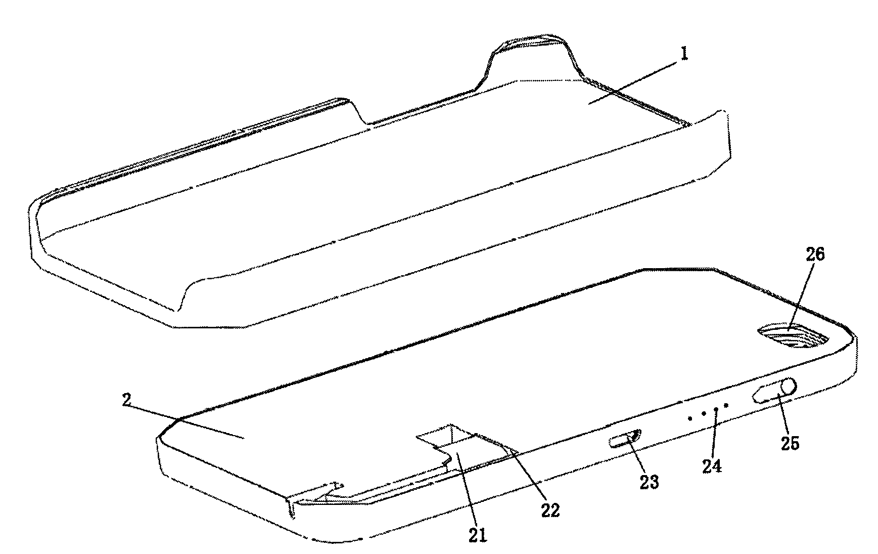
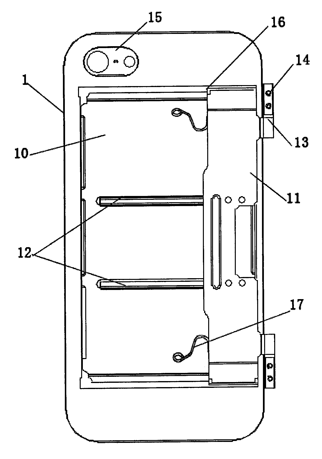
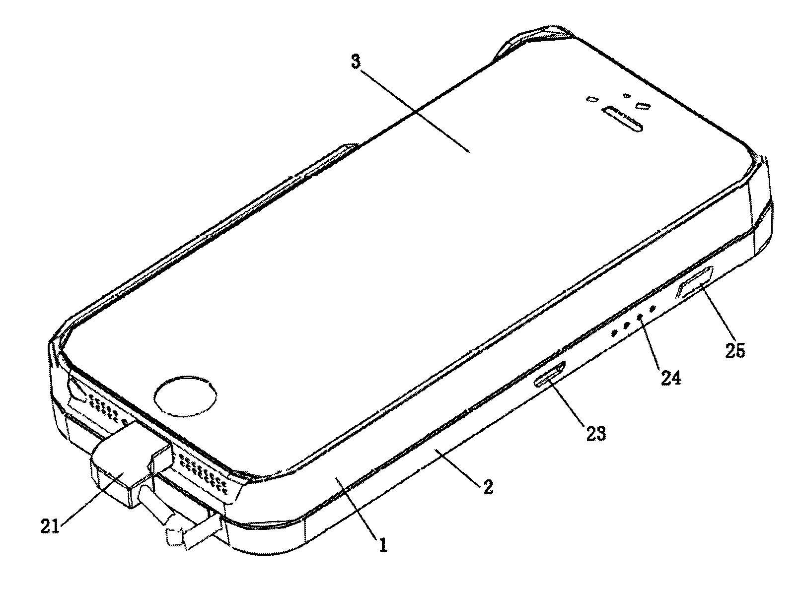
[0015] Such as Figure 1 to Figure 3 As shown, the present invention provides a side-sliding side-standing rotatable back clip battery structure, including an upper case (1), a lower case (2) and a metal sliding assembly connecting the upper case (1) and the lower case (2).

[0016] The structure of the upper shell (1) is used to attach and accommodate the mobile phone terminal (3) to physically protect the mobile phone. The upper shell (1) has a camera hole (15), and the lower shell (2) has a camera hole (26), so that the When the mobile phone is charging, it will not block the camera of the mobile phone, and will not affect the normal related photo taking, video calling or communication and video shooting functions of the mobile phone.

[0017] The lower case (2) has a built-in cell module and a circuit module. The circuit module mainly includes circuit structures such as a main...


PUM


Abstract

The invention discloses a sideslipping side-standing rotatable back-clamp battery structure which comprises an upper shell, a lower shell and a metal sliding component connecting the upper shell with the lower shell. A cellphone is contained in and protected physically by the upper shell, the lower shell comprises a battery module and a battery protecting plate, a battery and the battery protecting plate are sequentially connected to supply power emergently, the metal sliding component comprises a fixed plate, a sliding plate and a damping part to realize functions of sideslipping and 0-90 degree free rotating of the cellphone, the sliding plate is fixed on the upper shell, and the fixed plate is connected with the lower shell through lower edge fixing holes. The sideslipping side-standing rotatable back-clamp battery structure is simple in structure, portable due to the fact that the whole device can be folded, and high in operating flexibility due to the fact that the cellphone can realize sideslipping and rotating, and user experience is improved; due to the concealed design of an output line, troubles of line carrying and line finding are reduced for users, and compactness and attractiveness of products are improved.

Description

technical field [0001] The invention relates to a novel mobile phone back clip battery structure, in particular to a mobile phone back clip battery structure capable of side sliding cover, the upper cover can stand sideways and rotate at any angle, and the power output line is hidden in the main body. Background technique [0002] At present, the common mobile phone back clip battery on the market is to directly put the mobile phone in it, which plays the role of physically protecting the mobile phone and charging and protecting it anytime and anywhere, but it cannot be placed sideways and rotated at any angle. Freely adjustable mobile phone holder. At the same time, most of the output lines of the back clip battery are inlaid on the side or end surface of the back clip battery with noodle lines or spring wires. This explicit design artificially divides the back clip battery into several parts, which destroys the overall appearance of the back clip battery. The exposure of ...

Claims


Application Information

Patent Timeline
IPC IPC(8): H04M1/02H01M2/10H01M50/224H01M50/242H01M50/247
CPCH04M1/0274H04M1/185Y02E60/10H01M50/224H01M50/247H01M50/242
Inventor 姜红军
Owner 姜红军
Learn More