Electromagnetic friction stir spot welding device and method thereof

An electromagnetic stirring and friction point technology, which is applied in non-electric welding equipment, welding equipment, metal processing equipment, etc., can solve the problems of unsatisfactory degree of recrystallization structure refinement, withdrawing from the concave hole, and exiting the concave hole in the existing process. The effect of improving the microstructure, improving the plastic flow ability and improving the overall quality

Inactive Publication Date: 2013-06-26
SHANGHAI DIANJI UNIV
View PDF6 Cites 19 Cited by
  • Summary
  • Abstract
  • Description
  • Claims
  • Application Information

AI Technical Summary

Problems solved by technology

[0007] The present invention is aimed at the prior art, the microstructure morphology and grain size of the stirring zone, the thermomechanical affected zone and the heat affected zone in the friction stir spot welding joint have an important influence on the mechanical properties of the joint such as tensile shear and fatigue, while The existing refinement degree of recrystallized structure can not meet the needs of the existing...

Method used


Image

  • Electromagnetic friction stir spot welding device and method thereof
  • Electromagnetic friction stir spot welding device and method thereof
  • Electromagnetic friction stir spot welding device and method thereof

Examples


Embodiment Construction

[0025] In order to describe in detail the technical content, structural features, achieved objectives and effects of the present invention, the following will be described in detail in conjunction with embodiments and accompanying drawings.

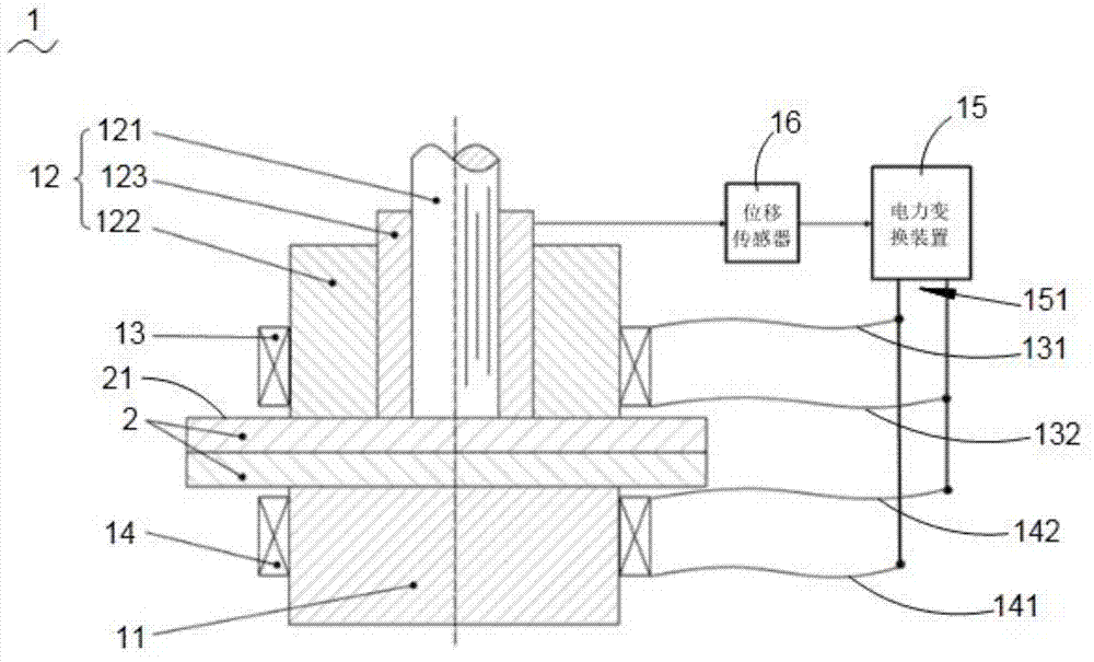
[0026] See figure 1 , figure 1 Shown is the structural schematic diagram of the electromagnetic friction stir spot welding device of the present invention. The electromagnetic friction stir spot welding device 1 includes a welding pad 11, the welding pad 11 is used to carry the plate 2 to be welded; a stirring head 12, the stirring head 12 is used to weld the plate 2 to be welded, And further includes a stirring needle 121 arranged in the inner layer of the stirring head 12, a clamping sleeve 122 arranged on the outer layer of the stirring head 12, and a stirring needle 121 and the clamping sleeve 122 arranged between The stirring sleeve 123, the stirring needle 121, the stirring sleeve 123, and the clamping sleeve 122 are arranged on the sa...


PUM


Abstract

The invention relates to an electromagnetic friction stir spot welding device which comprises a welding cushion block, a stirring head, a stirring needle, a clamping sleeve, a stirring sleeve, a first excitation coil, a second excitation coil, a power transformation device and a displacement sensor, wherein the stirring needle is arranged at the inner layer of the stirring head, the clamping sleeve is arranged at the outer layer of the stirring head, the stirring sleeve is arranged between the stirring needle and the clamping sleeve, the first excitation coil and the second excitation coil are respectively arranged on the clamping sleeve and the welding cushion block and are symmetrically distributed, the power transformation device is electrically connected with the first excitation coil and the second excitation coil, and the displacement sensor is electrically connected with the stirring sleeve and the power transformation device. According to the electromagnetic friction stir spot welding device, the power transformation device provides a strong magnetic field for welding materials in a molten state in a pressing-in stage, a refilling stage and a forging and pressing process, and thus the plastic flow capacity of the welding materials in the molten state is remarkably improved, the welding condition of a joint is improved, a re-crystallized grain is further refined, the microstructure morphology of a spot welding joint is improved, and the quality of the spot welding joint is improved.

Description

Technical field [0001] The invention relates to welding technical equipment, in particular to an electromagnetic friction stir spot welding device and a method thereof. Background technique [0002] Friction Stir Spot Welding (FSSW) is an innovative welding technology recently researched and developed on the basis of "linear" friction stir welding. FSSW can form spot welded lap joints, and its weld appearance is similar to resistance spot welding commonly used in aluminum alloy components, so it has high application value and research significance [0003] Currently, two different FSSW technologies have been reported in publicly available materials. The first method is the friction stir spot welding invented in 1993 by the Japanese Mazda Automobile Company. This friction stir spot welding is also called "friction stir spot welding with exit holes" technology. The welding equipment used is the same as ordinary friction stir welding. The equipment is similar, and the specific weldi...

Claims


Application Information

Patent Timeline
IPC IPC(8): B23K20/12B23K20/06
Inventor 杨洪刚
Owner SHANGHAI DIANJI UNIV
Why Eureka
Try Eureka