Control method and control system of pulse width modulation (PWM) signals and numerical control laser processing machine tool

A PWM signal and control method technology, applied in digital control, manufacturing tools, laser welding equipment, etc., can solve the problems of PWM signal change speed lag, long processing time, inaccurate cutting, etc., to achieve real-time change and shorten delay , to avoid the effect of hysteresis

Inactive Publication Date: 2013-06-19
HANS LASER TECH IND GRP CO LTD
View PDF4 Cites 4 Cited by
  • Summary
  • Abstract
  • Description
  • Claims
  • Application Information

AI Technical Summary

Problems solved by technology

[0005] The purpose of the embodiments of the present invention is to provide a PWM signal control method, aiming to solve the problem that the current PLC unit controls the PWM signal change processing time is too long, and the PWM signal change speed lags behind the machine tool running speed, resulting in inaccurate cutting.

Method used


Image

  • Control method and control system of pulse width modulation (PWM) signals and numerical control laser processing machine tool
  • Control method and control system of pulse width modulation (PWM) signals and numerical control laser processing machine tool
  • Control method and control system of pulse width modulation (PWM) signals and numerical control laser processing machine tool

Examples


Embodiment Construction

[0023] In order to make the object, technical solution and advantages of the present invention clearer, the present invention will be further described in detail below in conjunction with the accompanying drawings and embodiments. It should be understood that the specific embodiments described here are only used to explain the present invention, not to limit the present invention.

[0024] In the embodiment of the present invention, the CNC system directly controls the PWM unit to change the pulse signal frequency and duty cycle, which greatly shortens the delay of the pulse signal and makes laser cutting more accurate.

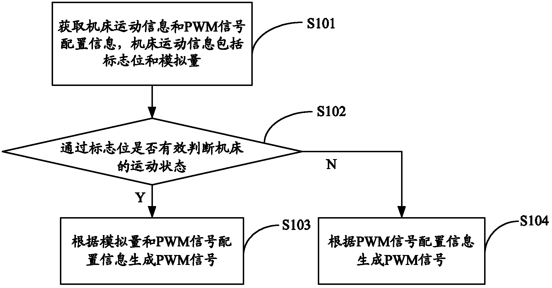
[0025] figure 1 The implementation flow of the PWM signal control method provided by the first embodiment of the present invention is shown, and for the convenience of description, only the parts related to the present invention are shown.

[0026] As an embodiment of the present invention, the PWM signal control method includes the following steps:

[0027...


PUM


Abstract

The invention relates to the field of numerical control laser processing, and provides a control method and a control system of pulse width modulation (PWM) signals and a numerical control laser processing machining tool. The control method of the PWM signals comprises the following steps: acquiring machine tool motion information and PWM signal configuration information, wherein the machine tool motion information comprises zone bit which shows machine tool motion state and analog quantity which changes in proportion with machine tool motion speeds, judging the machine tool motion state according to the zone bit, if the machine tool is in a motion state, the PWM signals are generated according to the analog quantity and the PWM signal configuration information; and if the machine tool is in a static state, the PWM signals are generated according to the PWM signal configuration information. A computer numerical control (CNC) system is used for directly controlling the PWM signals to control a system to carry out change of pulse signal frequency and duty cycle, delay of pulse signals is shortened, lag caused by programmable logic controller (PLC) cycle operation time is avoided, and cutting effect and cutting accuracy are improved effectively.

Description

technical field [0001] The invention belongs to the field of numerical control laser processing, and in particular relates to a PWM signal control method and system and a numerical control laser processing machine tool. Background technique [0002] Compared with traditional plate cutting, laser cutting technology has been widely promoted due to its narrow slit, small heat-affected zone, and high controllability. Usually, in order to obtain better cutting results, the laser is installed on the machine tool. Laser signals with different frequencies and duty ratios are used for cutting on different tracks, for example, pulse perforation is used for perforation, continuous laser signal is used for straight line cutting, and a certain angle can be used according to the radian of the required corner when cutting corners. Frequency and duty cycle laser signal cutting. [0003] At present, when the CNC system (Computerized Numerical Control, CNC) changes the running speed of the m...

Claims


Application Information

Patent Timeline
Patent Type & Authority Applications(China)
IPC IPC(8): G05B19/18B23K26/36
Inventor 余锦望向水平甘杰家邓超高云峰
Owner HANS LASER TECH IND GRP CO LTD
Why Eureka
Try Eureka