Device for producing crystal glass

A crystal glass and blast furnace technology, which is applied in glass forming, glass production, glass manufacturing equipment, etc., can solve the problems of operator injury, low production efficiency, high product cost, etc., to reduce energy consumption, improve production efficiency, and reduce defective products. The effect of yield reduction

Inactive Publication Date: 2013-06-19
宜城市大平水晶工艺品有限公司
View PDF5 Cites 5 Cited by
  • Summary
  • Abstract
  • Description
  • Claims
  • Application Information

AI Technical Summary

Problems solved by technology

Its obvious shortcomings are: 1. The structure of blast furnace design is not reasonable enough
Although the blast furnace with circular structure design has good product quality, it consumes a lot of energy, the product cost is high, and the damage to the inner hall wall of the blast furnace is relatively large; 2. The crystal glass generated after the silicate reaction is manually operated During the compression molding process, it is easy to cause injury to the operator, and the production efficiency is low; 3. The formed product is manually annealed, and the crystal glass is often broken due to uneven annealing. Not only is the product yield low, but it is also easy to hurt the human body

Method used


Image

  • Device for producing crystal glass
  • Device for producing crystal glass
  • Device for producing crystal glass

Examples


Embodiment 1

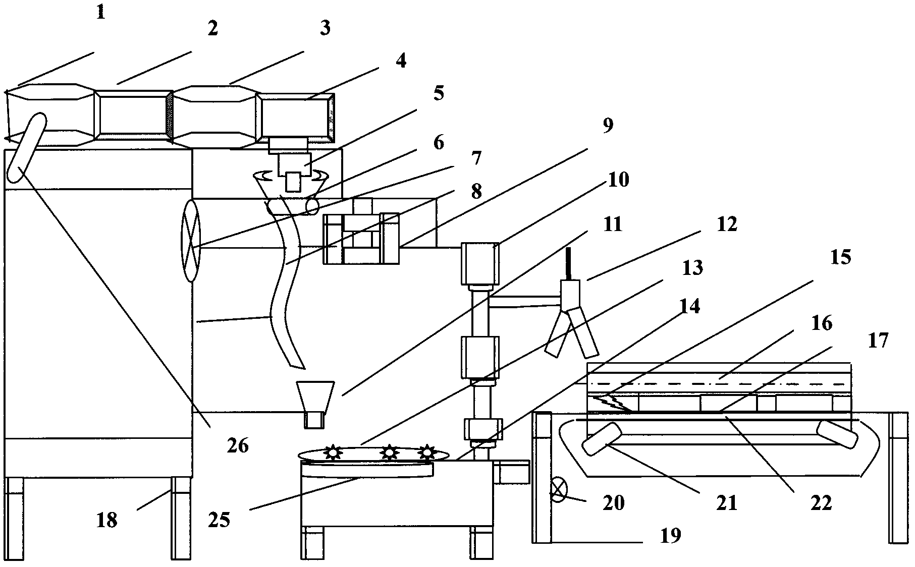
[0044] Such as figure 1 As shown, the blast furnace mainly includes a chemical tank 1, a clarification tank 2, a working room 3, a discharge tank 4, and a heating rod 26;

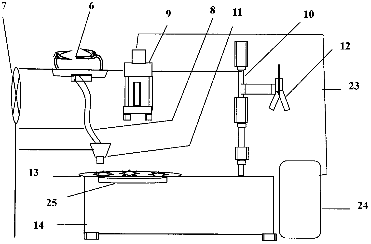
[0045] The heating rod 26 is placed in the chemical tank 1, and the heating rod 26 is connected to the power controller of the blast furnace through a wire; the chemical tank 1, the clarification tank 2, the working room 3, and the discharge tank 4 of the blast furnace are connected in sequence, and the middle is designed with The connection channel is designed with a discharge port 5 at the lower end of the discharge pool 4, and the discharge port 5 corresponds to the upper end of the guide groove 8 of the molding device;

[0046] Chemical tank 1, clarifying tank 2, working room 3, and discharging tank 4 are designed as a square structure, which is made of refractory materials. 20-30cm lower;

[0047] The chemical tank 1 is designed to be open to monitor the reaction of the material, and the clarifier 2,...

Embodiment 2

[0060] Such as figure 1 As shown, the blast furnace mainly includes a chemical tank 1, a clarification tank 2, a working room 3, a discharge tank 4, and a heating rod 26;

[0061] The heating rod 26 is placed in the chemical tank 1, and the heating rod 26 is connected to the power controller of the blast furnace through a wire; the chemical tank 1, the clarification tank 2, the working room 3, and the discharge tank 4 of the blast furnace are connected in sequence, and the middle is designed with The connection channel is designed with a discharge port 5 at the lower end of the discharge pool 4, and the discharge port 5 corresponds to the upper end of the guide groove 8 of the molding device;

[0062] Chemical tank 1, clarifying tank 2, working room 3, and discharging tank 4 are designed as polygonal structures made of refractory materials. 40-50cm lower;

[0063] The chemical tank 1 is designed to be open to monitor the reaction of the material, and the clarifier 2, the wor...

Embodiment 3

[0075] Embodiment three is the best embodiment;

[0076] Such as figure 1 As shown, the blast furnace mainly includes a chemical tank 1, a clarification tank 2, a working room 3, a discharge tank 4, and a heating rod 26;

[0077] The heating rod 26 is placed in the chemical tank 1, and the heating rod 26 is connected to the power controller of the blast furnace through a wire; the chemical tank 1, the clarification tank 2, the working room 3, and the discharge tank 4 of the blast furnace are connected in sequence, and the middle is designed with The connection channel is designed with a discharge port 5 at the lower end of the discharge pool 4, and the discharge port 5 corresponds to the upper end of the guide groove 8 of the molding device;

[0078] The chemical tank 1 and working room 3 are designed as polygonal shapes, and the clarification tank 2 and discharge tank 4 are designed as square structures, which are made of refractory materials. The lower end of pool 4 is 30-...


PUM


Abstract

The invention relates to a device for producing crystal glass. The device for producing the crystal glass mainly comprises a blast furnace, a compression moulding forming device and a precision quenching device. A support rod of the compression moulding forming device is connected with a support of the blast furnace, and a forming platform of the compression moulding forming device is connected with a support of the precision quenching device. A material melting pond, a sedimentation basin, a work chamber and a discharge pond of the blast furnace are connected in sequence. A discharge port is formed at the lower end of the discharge pond. The compression moulding forming device mainly comprises a pair of scissors, a guide groove, a forming air cylinder, a mechanical arm, a forming platform, a mould, an air pump and a program control circuit controller. The upper end of the guide groove corresponds to the discharge port. The precision quenching device mainly comprises a motor, a conveyer belt, an insulating layer, a heating plate, a temperature sensor and a circuit controller. An opening at the left end of the precision quenching device corresponds to the mechanical arm of the compression moulding forming device. Compared with the prior art, the device for producing the crystal glass has the advantages that the reaction temperature of silicate can be reduced by 20-40 DEG C, energy consumption is reduced by about 10%, the production efficiency is enabled to be improved by more than 30%, and the rate of defective goods is reduced by more than 15 percent points.

Description

Technical field: [0001] The invention relates to a device for producing glass, in particular to a device for producing crystal glass. Background technique: [0002] Crystal glass is known as the "Queen of Ornaments" because of its crystal clear, clean and bright. At present, it has been widely used to make high-end lamp holders, lampshades, walls, railings, hand ornaments and other products. The history of producing crystal glass in the world can be traced back to the beginning of the 19th century. my country began to develop this product in the 1960s, and it began to take shape in the 1980s, with more than 200 varieties. From the point of view of the current production technology of crystal glass in my country, the silicate method is mainly used, that is, high-purity quartz sand is selected, and then a small amount of other mineral salts are added. Silicate reaction occurs under high-temperature melting conditions to form glass, and then through Molding, gradual annealing a...

Claims


Application Information

Patent Timeline
IPC IPC(8): C03B20/00
CPCY02P40/57
Inventor 王俊郭发志李华刘青山
Owner 宜城市大平水晶工艺品有限公司
Why Eureka
Try Eureka