Laser processing device based on dynamic focusing

A dynamic focusing, laser processing technology, applied in laser welding equipment, metal processing equipment, optics, etc., can solve the problems of low position accuracy and can not meet the needs of high-speed and high-precision scanning

Active Publication Date: 2014-12-17
张立国
View PDF7 Cites 0 Cited by
  • Summary
  • Abstract
  • Description
  • Claims
  • Application Information

AI Technical Summary

Problems solved by technology

[0003] The problem in this technical solution is that, due to the large scanning range of the galvanometer, the distance between the laser focus and the galvanometer is relatively long, so the position accuracy of the laser focus controlled by the galvanometer scanning is low, and it cannot meet the local range of large-format laser scanning. High-speed and high-precision scanning requirements

Method used


Image

  • Laser processing device based on dynamic focusing
  • Laser processing device based on dynamic focusing

Examples


Embodiment 1

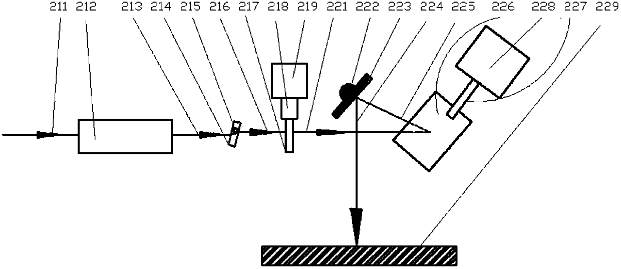
[0043] figure 1 Schematic diagram of the device structure for rapid prototyping of ultraviolet laser photocuring, such as figure 2 Shown: UV laser photocuring rapid prototyping device, including dynamic focusing mirror, beam fine scanning module and large format scanning module.

[0044] The dynamic focusing mirror has a wavelength of 355 nanometers, a central focal length of 1500 mm, and a focusing spot of 100 microns.

[0045] The beam fine scanning module includes two laser beam offset units, namely a first laser beam offset unit and a second laser beam offset unit, the first laser beam offset unit includes a first flat quartz glass 214 and is used to drive the The first motor of the first flat quartz glass 214, the first flat quartz glass 214 is installed on the motor shaft 215 of the first motor, and the axis of the motor shaft 215 of the first motor is perpendicular to the paper. The second laser beam offset unit includes a second flat quartz glass 217 and a second mo...

Embodiment 2

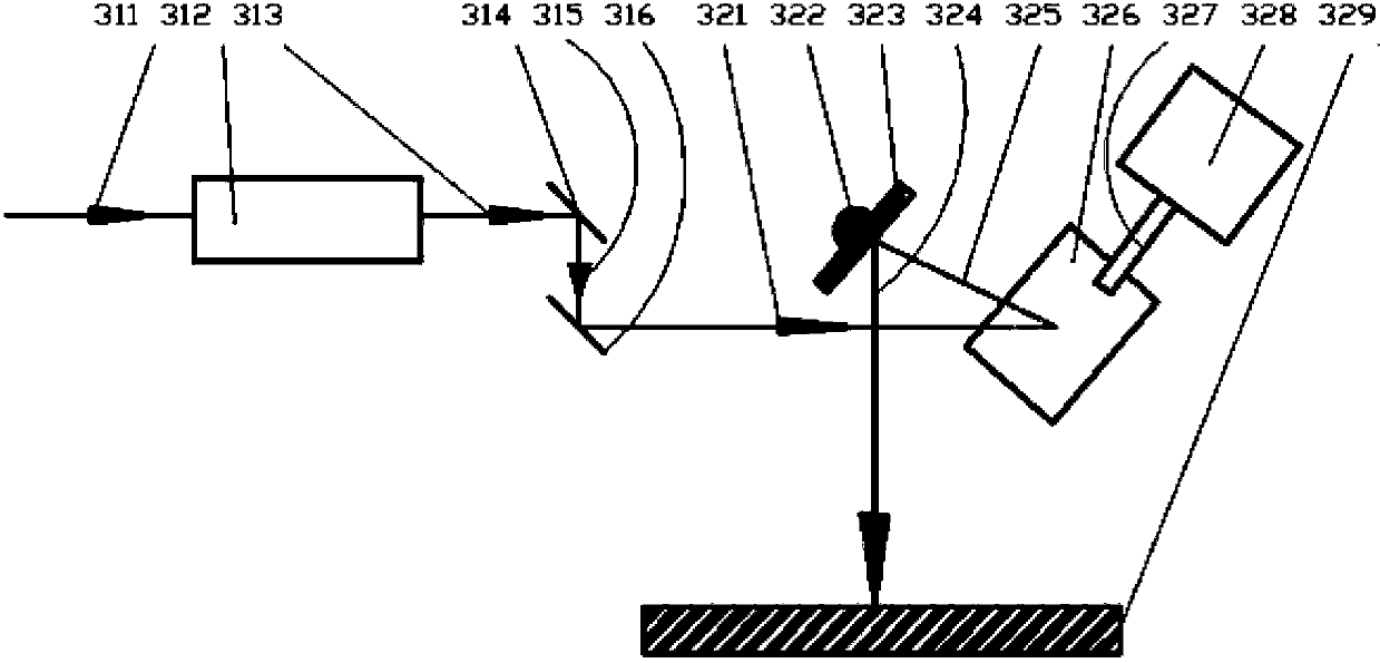
[0057] figure 2 Schematic diagram of the device structure for touch screen ITO film engraving, such as figure 2 Shown: The touch screen ITO film engraving device includes a dynamic focusing mirror, a beam fine scanning module and a large format scanning module.

[0058] The dynamic focusing mirror has a wavelength of 355nm and a central focal length of 1000mm.

[0059] The beam fine scanning module includes two laser beam offset units, namely a first laser beam offset unit and a second laser beam offset unit, the first laser beam offset unit includes a first plane mirror 314 and is used to drive the The first piezoelectric ceramic driving system (not shown in the figure) for the movement (swing or translation) of the first plane mirror 314, the second laser beam offset unit includes a second plane mirror 316 and is used to drive the first plane mirror 316 The second piezoelectric ceramic drive system (not shown in the figure) for the movement (swing or translation) of the ...


PUM

PropertyMeasurementUnit
wavelengthaaaaaaaaaa
frequencyaaaaaaaaaa
thicknessaaaaaaaaaa

Abstract

The invention provides a laser processing device based on dynamic focusing. The laser processing device comprises a dynamic focusing lens, a light beam fine scanning module and a big format scanning module, wherein the dynamic focusing lens completes dynamic focusing of a laser light beam and dynamically changes the distance between a laser focal point and the laser dynamic focusing lens. The light beam fine scanning module can complete scanning and controlling of a fine graph structure of a local area in a high-speed and high-precision mode, can complete filing and scanning of a local outline in a high-speed and high-precision mode, can help the big format scanning module conduct controlling of quickening and slowing down of the laser light beam, greatly reduces occupied time due to swinging, quickening and slowing down of lens of a vibration mirror of the big format scanning module, improves processing quality, and simultaneously keeps speed uniformity of motion of a laser focusing point on the surface of a workpiece. The big format scanning module keeps large format scanning laser processing ability.

Description

technical field [0001] The invention belongs to the field of laser processing, and in particular relates to a laser processing device of a laser dynamic focus scanning system which integrates laser high-speed fine scanning and large-format scanning. Background technique [0002] The 3D dynamic scanning focusing system is generally also called 3D dynamic scanning or 3D scanning system. In the three-dimensional dynamic scanning focusing system, the scanning galvanometer is placed behind the three-dimensional dynamic focusing mirror. The three-dimensional dynamic focusing mirror system generally includes a movable focusing lens lens group composed of one or more focusing lens lenses. The laser beam passes through the focusing lens. After the lens group, it is reflected by the scanning galvanometer, and finally reaches the focal plane. Use a transmission device to move part or all of the lenses along the optical axis to change the distance between the lenses, so that the positi...

Claims


Application Information

Patent Timeline
Patent Type & Authority Patents(China)
IPC IPC(8): B23K26/00B23K26/064B23K26/082G02B26/10G02B7/04B23K26/04
Inventor 张立国
Owner 张立国
Why Eureka
Try Eureka