
High overload and linear vibration composite test device

A technology for testing equipment and line vibration, applied in the field of inertial navigation testing, can solve problems such as burnout, complex equipment structure, and large volume, and achieve the effects of convenient debugging and maintenance, simplified equipment structure, and good manufacturing process.

Inactive Publication Date: 2015-07-08
HARBIN INST OF TECH
View PDF5 Cites 0 Cited by
  • Summary
  • Abstract
  • Description
  • Claims
  • Application Information

AI Technical Summary

Problems solved by technology

The current existing schemes are all composite environmental simulation test equipment with arm centrifuges as the main body. The general practice of this kind of equipment is to install a hanging basket at one end of the big arm of the centrifuge, and install vibration equipment in the hanging basket, but This kind of equipment has a complex structure and a large volume. It is mainly used in the fields of civil engineering and structural mechanics research, and is not suitable for the field of inertial instrument testing. In addition, equipment using this scheme needs to solve the problem of how the electromagnetic vibration equipment can work normally under large overload, otherwise There will be deflection of the electromagnetic moving coil under large overload, or even burn out

Method used


Image

  • High overload and linear vibration composite test device
  • High overload and linear vibration composite test device
  • High overload and linear vibration composite test device

Examples


Embodiment 1

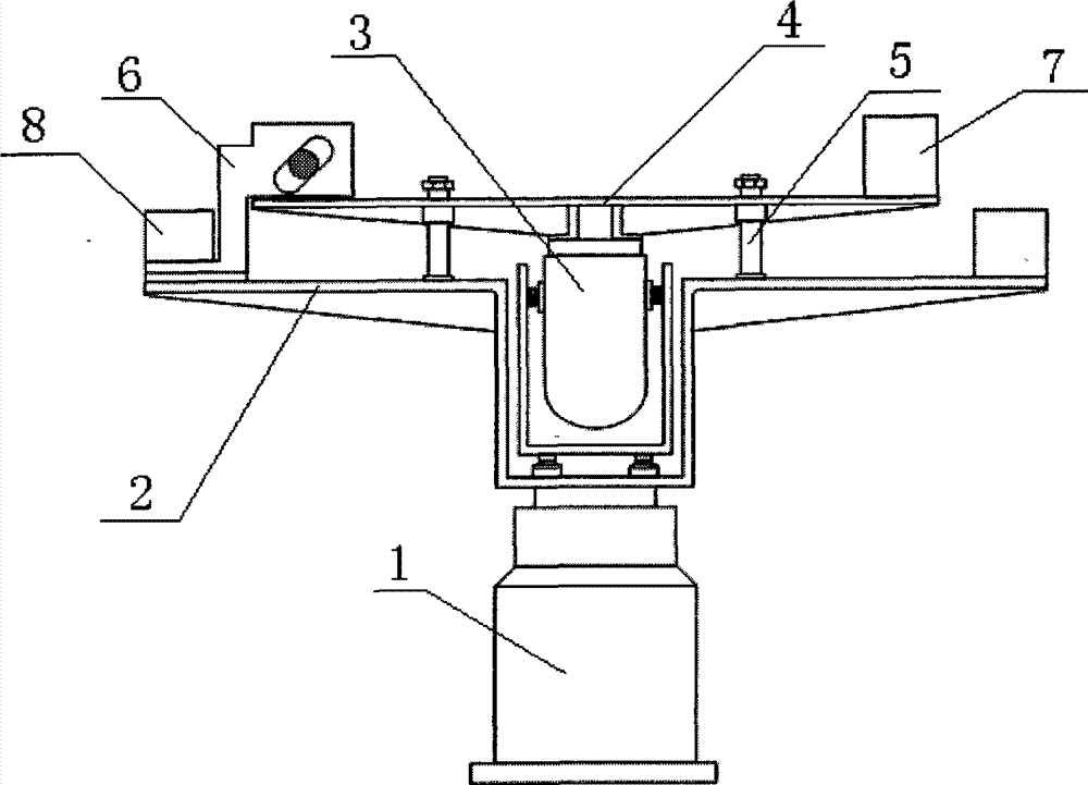
[0015] Example 1: Combining image 3 , the present invention is a large overload and linear vibration composite test device, which is composed of a disc centrifuge, a vibrating beam, a direction-changing fixture, etc., the direction-changing fixture is installed on the edge of the disc centrifuge, At the center of the disc centrifuge, the vibrator can be adjusted through the centering device, and the speed of the disc centrifuge and the vibration frequency of the vibrator can be adjusted.

[0016] 1. Horizontal vibration of the product under test - large overload compound movement

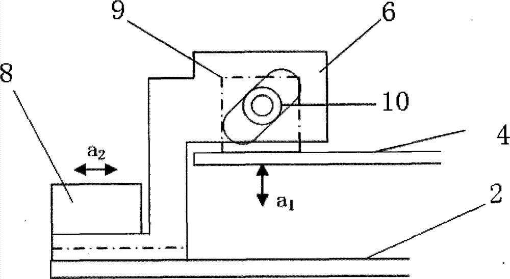
[0017] Such as figure 1 As shown, the vibrator is vertically installed in the center of the centrifuge, and the vibration source is transmitted to the product under test through the clamp on the vibrating beam. The fixture has variable guide grooves to change the vertical vibration of the vibrator into the horizontal vibration of the product under test.

[0018] The variable direction vibration ...


PUM


Abstract

The invention aims at providing a high overload and linear vibration composite test device which comprises a centrifugal machine, a centrifugal workbench, a vibration exciter, a vibrating beam, a vertical guider, a direction-variable clamp, a counter balance block and an instrument, wherein the centrifugal workbench is arranged on the centrifugal machine, the vibration exciter is arranged at the center part of a disc centrifugal machine, the vibrating beam is fixedly connected with the centrifugal workbench by the vertical guider, the direction-variable clamp is respectively connected with the vibrating beam and the left end of the centrifugal workbench, and the instrument is arranged on the direction-variable clamp. According to the composite test device, the test requirement on a high overload and linear vibration composite environment can be met, the device is simple in structure, parts are high in standardized rate, and the device is good in manufacturability and convenient to debug and maintain; the vibration exciter is arranged and positioned on the central axis of the centrifugal machine, an eccentric load is reduced by adjusting the center of the vibration exciter, and an outer housing of the vibration exciter rotates along with the centrifugal machine, so that the deviation rectifying problem of the vibration exciter under high overloads can be solved; and the horizontal vibration or the vertical vibration can be output under the condition that the vibration exciter installing position is not changed.

Description

technical field [0001] The invention relates to the technical field of inertial navigation testing, in particular to a large overload and linear vibration composite testing equipment. Background technique [0002] At present, in the environmental tests of many inertial instruments, there are requirements for the products to carry out combined environmental tests of large overload and linear vibration. Because aircraft, missiles, satellites, and spacecraft are subject to the compound environment of large overload and linear vibration during the launch and reentry stages, it is very important to study the influence of the compound environment on inertial instruments. However, for a long time, since there is no composite test equipment for large overload and line vibration, single environmental tests have been used instead for such problems, that is, vibration experiments are performed on the tested products using a shaking table, and then large overload experiments are perform...

Claims


Application Information

Patent Timeline
Patent Type & Authority Patents(China)
IPC IPC(8): G01C25/00
Inventor 于志伟刘雨曾鸣苏宝库
Owner HARBIN INST OF TECH
Learn More