Composite filter element assembly and water purifier

A composite filter element and component technology, applied in the field of water treatment, can solve the problems of complicated replacement of filter element components, water leakage, large occupied volume, etc.

Active Publication Date: 2021-09-10
PICOLEAD (BEIJING) WATER TREATMENT TECH CO LTD +1
View PDF0 Cites 0 Cited by
  • Summary
  • Abstract
  • Description
  • Claims
  • Application Information

AI Technical Summary

Problems solved by technology

The water purifiers currently on the market generally use the following filter element assemblies: one filter element assembly is filled with a single filter material. The components need to be equipped with fixed mounting seats, and need to be replaced and maintained separately, which not only occupies a large volume and high cost, but also requires complicated replacement of the filter element components, which seriously affects the user experience; another type of filter element component is a composite filter element component. The assembly is filled with at least two kinds of filter materials. It has a waterway inside to connect different filter materials in series. It has a water inlet and a water outlet outside. The water enters from the water inlet and passes through the inside of the filter element along the waterway Different filter materials flow out of the composite filter element assembly from the water outlet, but the use of this composite filter element assembly has certain limitations; there are also composite filter element assemblies that directly connect the shells of multiple filter element assemblies with a single filter material. Combination of filter materials with multiple filtering functions, but the connection of multiple filter element shells will form multiple exposed connection parts, so these connection parts will become multiple exposed water leakage hazards. Once the connection parts are sealed or If there is a problem with welding, there will be a risk of water leakage

Method used


Image

  • Composite filter element assembly and water purifier
  • Composite filter element assembly and water purifier
  • Composite filter element assembly and water purifier

Examples


Embodiment 1

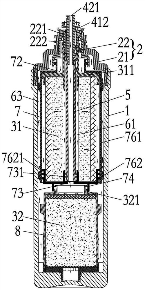
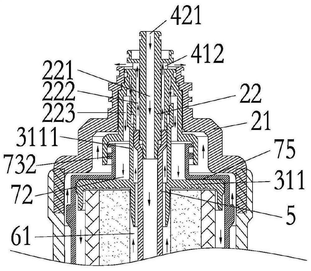
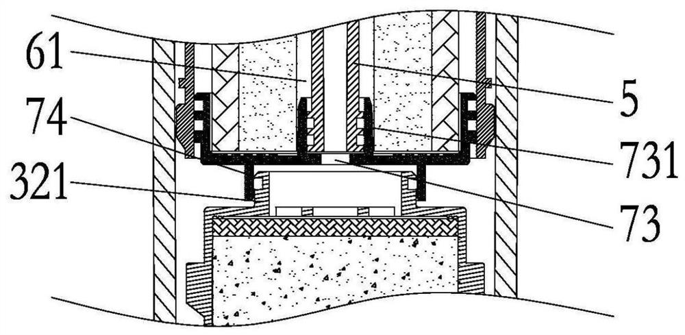
[0054] Such as Figure 1-Figure 5 As shown, a composite filter element assembly includes a housing 1 and an installation head 2, the installation head 2 is located at one end of the housing 1, the installation head 2 includes an outer end cover 21, and the filter material inside the filter element assembly is loaded into the housing through the opening at the upper end of the housing 1 1, the outer end cover 21 is welded and fixed on the opening of the upper end of the shell 1. The composite filter element assembly also includes a first filter element 31 and a second filter element 32 , wherein the first filter element 31 and the second filter element 32 are arranged axially, and the first filter element 31 is located between the second filter element 32 and the installation head 2 . The first filter element 31 and the second filter element 32 are respectively located in the first waterway and the second waterway, wherein the first waterway and the second waterway are separate...

Embodiment 2

[0073] Such as Figure 9-Figure 13As described above, a composite filter element assembly includes a housing 1a and an installation head 2a, the installation head 2a is located at one end of the housing 1a, and the installation head 2a includes an outer end cover 21a and a waterway converter 22a. The composite filter element assembly also includes a first filter element 31a and a second filter element 32a, wherein the first filter element 31a and the second filter element 32a are arranged axially, and the first filter element 31a is located between the second filter element 32a and the installation head 2a. The first filter element 31a and the second filter element 32a are respectively located in the first waterway and the second waterway, wherein the first waterway and the second waterway are separated from each other, the first waterway includes a first water inlet 411a and a first water outlet 412a, and the first waterway includes a first water inlet 411a and a first water o...

Embodiment 3

[0082] Such as Figure 14-Figure 17 As shown, a composite filter assembly includes a housing 1b and an installation head 2b, the installation head 2b is located at one end of the housing 1b, and the installation head 2b includes an outer end cover 21b and a waterway converter 22b. The composite filter element assembly also includes a first filter element 31b and a second filter element 32b, wherein the first filter element 31b and the second filter element 32b are arranged axially, and the first filter element 31b is located between the second filter element 32b and the installation head 2b. The first filter element 31b and the second filter element 32b are respectively located in the first waterway and the second waterway, wherein the first waterway and the second waterway are separated from each other, the first waterway includes a first water inlet 411b and a first water outlet 412b, and the first waterway includes a first water inlet 411b and a first water outlet 412b. The...


PUM


Abstract

The invention discloses a composite filter element assembly, comprising a casing and an installation head, the installation head is located at one end of the casing, and the installation head comprises an outer end cover and a water circuit converter; the first filter element and the second filter element are arranged along the axial direction, and the first filter element is located at the Between the two filter elements and the installation head; the first filter element and the second filter element are respectively located in the first water channel and the second water channel separated from each other, the first water channel and the second water channel respectively include a first water inlet and outlet and a second water inlet and outlet, the first water channel and the second water channel respectively The first water inlet and outlet and the second water inlet and outlet are located on the installation head; the central pipe runs through the first filter element and connects the second filter element with one of the second water inlet and outlet, the interior of the central pipe constitutes a part of the second waterway, and the outer wall of the central pipe is connected to The water passage between the first filter elements constitutes a part of the first water path; the water path converter is located at the upper end of the first filter element and is provided with a flow channel, the flow channel includes a central flow channel, and one end of the central flow channel is one of the second water inlets and outlets , and the other end is connected to the central tube. The invention belongs to the field of household water purification.

Description

technical field [0001] The invention relates to a composite filter element assembly and a water purifier, belonging to the technical field of water treatment. Background technique [0002] Water is an important part of the human body. The water in the human body accounts for about 50% of an adult's body weight. The average daily water consumption of a normal person is 2000-2500 ml, and the oxidation of substances in the body can produce 300 ml of water, so it should be replenished every day About 2000 ml of water, most of which are obtained through drinking water. However, with the continuous aggravation of water pollution, it is becoming more and more difficult to drink healthy water, and other organs of the human body will also be damaged due to long-term pollution. The tap water for daily drinking has gone through a variety of cleaning, sterilization and disinfection methods, and the water quality test at the factory can meet the national hygiene standards, and then flow...

Claims


Application Information

Patent Timeline
Patent Type & Authority Patents(China)
IPC IPC(8): B01D29/52B01D24/00B01D36/02C02F9/02
CPCB01D24/002B01D29/52B01D36/02C02F1/441C02F9/00
Inventor 那勤夫朱泽春方锡奉刘宗印金海军赵慧斌
Owner PICOLEAD (BEIJING) WATER TREATMENT TECH CO LTD
Why Eureka
Try Eureka