
Waste plastic friction cleaning machine

A friction cleaning machine, waste plastic technology, applied in the direction of plastic recycling, cleaning methods and utensils, filter screens, etc., can solve the problems of easy clogging of the screen, equipment shutdown and maintenance, etc., to solve the problem of screen clogging, effective friction cleaning, and simple structure. Effect

Inactive Publication Date: 2013-06-12
ZHANGJIAGANG BEIER MACHINERY
View PDF0 Cites 12 Cited by
  • Summary
  • Abstract
  • Description
  • Claims
  • Application Information

AI Technical Summary

Problems solved by technology

[0004] The technical problem to be solved by the present invention is: to provide a friction cleaning machine for waste plastics, which has the function of fully friction cleaning materials and at the same time solves the problem that the screen is easily blocked and causes unnecessary downtime and maintenance of the equipment

Method used


Image

  • Waste plastic friction cleaning machine
  • Waste plastic friction cleaning machine
  • Waste plastic friction cleaning machine

Examples


Embodiment Construction

[0012] 1. Start without load, check whether the steering of the motor (16) is correct, connect the rotary joint (1) and drain water, and run idling for 3-5 minutes after starting up.

[0013] 2. Put the material into the feed port (5), and enter the barrel (9) through the main shaft (6) driven by the motor (16) for cleaning. Finally, the cleaned material enters the next machine through the discharge port (14). Processing in the cleaning phase.

[0014] 3. The present invention can be used alone or connected in series to the production line. It can be controlled automatically and individually when used in the production line.

[0015] 4. The present invention does not need to fully open the rotary joint (1) when in use, but to use intermittent water, open the water inlet ball valve after 2 hours of work, and flush the holes of the screen (8). After half an hour of flushing, the water inlet can be closed ball valve.

[0016] 5. Due to the high speed of the present invention, l...


PUM


Abstract

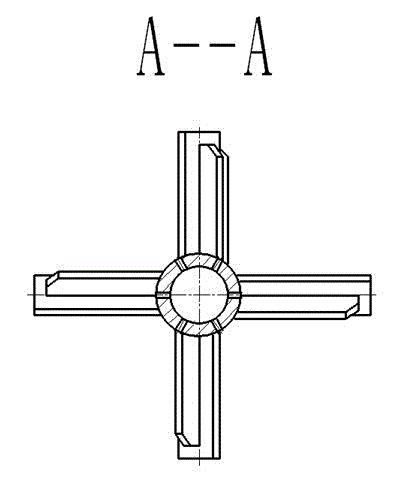
The invention provides a waste plastic friction cleaning machine, relating to the cleaning and recycling of waste plastic and applicable to the stage of further removing residual oil contamination and viscose of plastic bottles, sheets and films treated by a heat cleaning machine. The waste plastic friction cleaning machine mainly comprises a motor (16), a rotary joint (1), a screen (8), a spindle (6), a machine barrel (9), a rack (18) and the like. The waste plastic friction cleaning machine is simple in structure, and more excellent in friction cleaning effect on materials, and the problem that the screen is easily plugged can be solved. When the motor (16) drives the spindle (6) to rotate at high speed, materials entering the machine barrel (9) from a feeding inlet (5) are separated from dirt, the dirt is penetrated through the screen (8) under the double actions of strong centrifugal force and the high-pressure showering formed by a plurality of holes in the main spindle (6) and is discharged out through a water discharge outlet (20) along with water flow, while the materials are blocked in the screen (8) and spirally travels to a discharge outlet (14) under the driving of shifting plates distributed in a spiral line, so as to enter next cleaning stage.

Description

technical field [0001] The invention relates to cleaning and recovery of waste plastics, which is applicable to the stage of further removing residual oil stains and viscose after plastic bottles, sheets and films are processed by a thermal cleaning machine. Background technique [0002] Today, as the price level continues to rise, both energy prices and material prices are increasing, and the competition among manufacturers in the plastic machine industry is becoming more and more fierce, which urgently requires us to continuously innovate technologies and develop new products. Only by reducing production costs and energy consumption under the premise of ensuring quality can the company's market competitiveness in similar equipment be improved. [0003] At present, most of the high-speed friction cleaning machines used, the main shaft adopts a disconnected spiral, and a row of water inlet pipes is arranged above the equipment. When the main shaft rotates at high speed, the ...

Claims


Application Information

Patent Timeline
Patent Type & Authority Applications(China)
IPC IPC(8): B29B17/00B08B7/00B07B1/55
CPCB29K2105/065B29L2007/008B29B2017/0289B29B17/02Y02W30/62
Inventor 何德方唐志良
Owner ZHANGJIAGANG BEIER MACHINERY
Learn More