Control method and device for fuel cell system
The technology of a fuel cell system and control method, which is applied in the field of communication, can solve the problems of low efficiency in restoring battery stack performance, achieve the effects of improving performance and durability, and eliminating flooding
- Summary
- Abstract
- Description
- Claims
- Application Information
AI Technical Summary
Problems solved by technology
Method used
Image
Examples
Embodiment approach 1
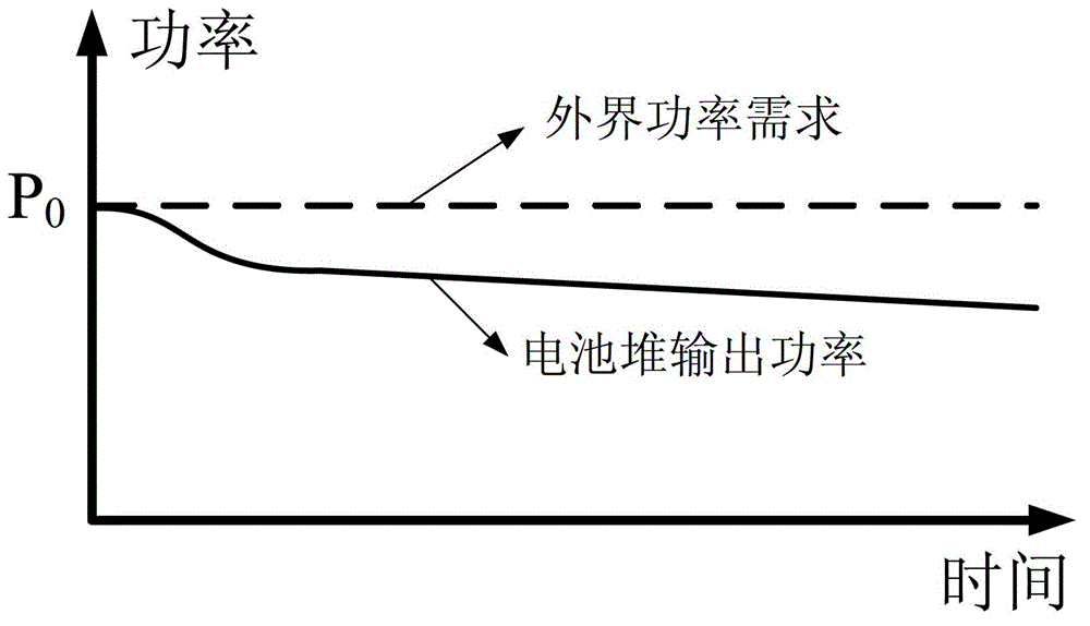
[0049] Such as Image 6 As shown, when the output power of the battery stack temporarily drops, the fuel cell system does not increase the gas flow of the reaction and maintains the operating state of the BOP, while the part of the external power demand that exceeds the output power of the battery stack is provided by the energy storage unit. At this time, the supply of the reaction gas of the battery stack is greater than the normal flow rate of the reaction gas required, which facilitates the discharge of liquid water inside the battery stack, so that the battery stack can return to the normal power output state. However, while the performance of the battery stack is recovering, the power provided by the energy storage unit is gradually reduced until the output power of the battery stack can just meet the external power demand during normal operation.
Embodiment approach 2
[0051] Such as Figure 7 As shown, when the output power of the battery stack temporarily drops, the fuel cell system does not increase the gas flow of the reaction, and maintains the operating state of the BOP. Preferably, the output power of the battery stack is further reduced to reduce the output burden of the battery stack. At this time, the part of the external power demand greater than the output power of the battery stack is provided by the energy storage unit. At this time, the supply of reaction gas to the battery stack is much greater than the normal required flow of reaction gas, which facilitates the rapid discharge of liquid water inside the battery stack, so that the battery stack can return to the normal power output state. However, while the performance of the battery stack is recovering, the power provided by the energy storage unit is gradually reduced until the output power of the battery stack can just meet the external power demand when the battery stack ...
Embodiment approach 3
[0055] When the output power of the battery stack temporarily drops, the fuel cell system does not increase the reactant gas flow and maintains the BOP operating state, while the power required by the BOP module is provided by the energy storage unit (that is, as Figure 8 d in), thus reducing the required power output of the battery stack. At this time, the supply of reaction gas to the battery stack is greater than the normal flow rate of reaction gas required, which facilitates the discharge of liquid water inside the battery stack and restores the battery stack to a normal state. While the performance of the battery stack is restored, the power demand of the BOP module is provided by the battery stack again (ie, if Figure 8 Shown in e), until the normal operation of the battery stack just meets the internal and external power requirements of the system.
PUM
 Abstract
Description
Claims
Application Information
 - R&D
- Intellectual Property
- Life Sciences
- Materials
- Tech Scout
- Unparalleled Data Quality
- Higher Quality Content
- 60% Fewer Hallucinations
Browse by: Latest US Patents, China's latest patents, Technical Efficacy Thesaurus, Application Domain, Technology Topic, Popular Technical Reports.
© 2025 PatSnap. All rights reserved.Legal|Privacy policy|Modern Slavery Act Transparency Statement|Sitemap|About US| Contact US: help@patsnap.com


